Processor module, Removing the processor module – Dell Latitude D830 (Early 2007) User Manual
Page 13
Back to Contents Page
Processor Module
Dell™ Latitude™ D830 Service Manual
Installing the Processor Module
Removing the Processor Module
1.
Follow the procedures in
Before You Begin
.
2.
Remove the hinge cover (see
Hinge Cover
).
3.
Remove the keyboard (see
Keyboard
).
4.
Remove the display assembly (see
Display Assembly
).
5.
Remove the palm rest (see
Palm Rest
).
6.
Remove the processor thermal-cooling assembly (see
Processor Thermal-Cooling Assembly
).
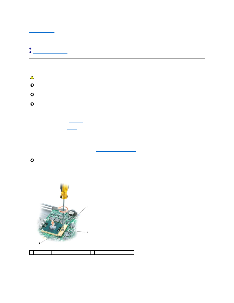
7.
To loosen the ZIF socket, use a small, flat-blade screwdriver and rotate the ZIF-socket cam screw counterclockwise until it comes to the cam stop.
The ZIF-socket cam screw secures the processor to the system board. Take note of the arrow on the ZIF-socket cam screw.
8.
Use a processor extraction tool to remove the processor module.
CAUTION:
Before performing the following procedures, follow the safety instructions in the Product Information Guide.
NOTICE:
To avoid electrostatic discharge, ground yourself by using a wrist grounding strap or by periodically touching a connector on the back
panel of the computer.
NOTICE:
Press and hold the processor down by applying slight pressure to the center of the processor while turning the cam screw to prevent
intermittent contact between the cam screw and processor.
NOTICE:
To avoid damage to the processor, hold the screwdriver so that it is perpendicular to the processor when turning the cam screw.
NOTICE:
When removing the processor module, pull the module straight up. Be careful not to bend the pins on the processor module.
1
ZIF-socket
2
ZIF-socket cam screw
3
pin-1 corner of processor