Docking connector – Dell Inspiron 4000 User Manual
Page 14
transmits data in parallel format, where 8 data bits (one byte) are sent simultaneously over eight separate lines.
The parallel connector can also be configured for compatibility with the PS/2 standard. Support for the EPP feature improves network adapter performance
(adapters connect to the computer's parallel connector and require the appropriate software drivers from the adapter's manufacturer).
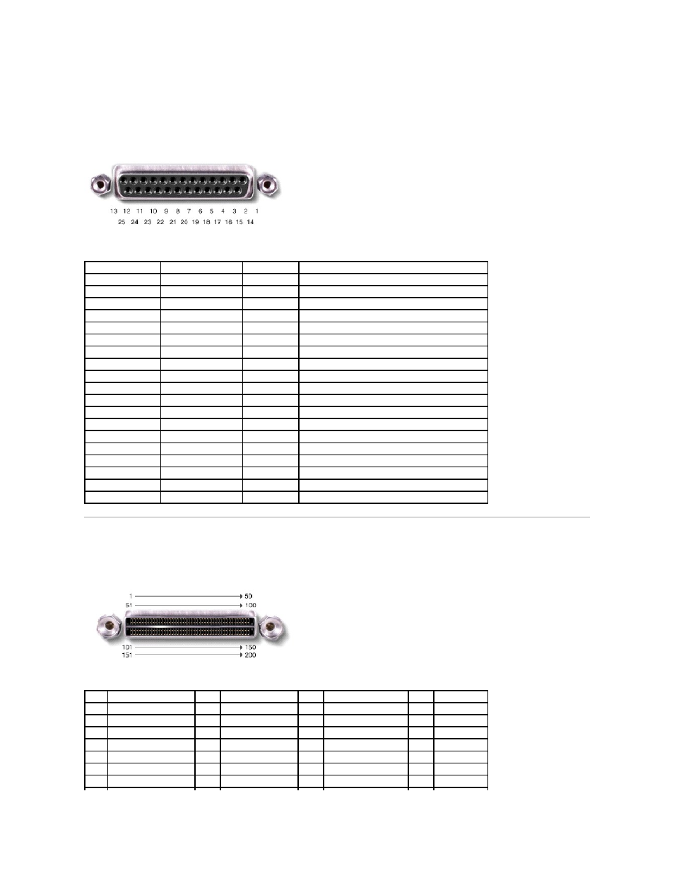
If you reconfigure your hardware, you may need pin number and signal information for the parallel connector.
Docking Connector
Use this connector to attach your computer to the optional port replicator.
Pin
Signal
I/O
Definition
1
STB#
I/O
Strobe
2
D0
I/O
Printer data bit 0
3
PD1
I/O
Printer data bit 1
4
PD2
I/O
Printer data bit 2
5
PD3
I/O
Printer data bit 3
6
PD4
I/O
Printer data bit 4
7
PD5
I/O
Printer data bit 5
8
PD6
I/O
Printer data bit 6
9
PD7
I/O
Printer data bit 7
10
ACK#
I
Acknowledge
11
BUSY
I
Busy
12
P E
I
Paper end
13
SLCT
I
Select
14
AFD#
O
Automatic feed
15
ERR#
I
Error
16
INIT#
O
Initialize printer
17
SLIN#
O
Select in
18-25
N/A
N/A
Ground signal
Shell
N/A
N/A
Frame ground
Pin
Signal
Pin
Signal
Pin
Signal
Pin
Signal
1
STRB#/5V
51
HSYNC
101
VGA_GRN
151
GND
2
PD0
52
VSYNC
102
GND
152
CLK_SPCI
3
PD1
53
GND
103
VGA_RED
153
GND
4
PD2
54
DOCKED
104
GND
154
SAD0
5
PD3
55
USB_VD1+
105
VGA_BLU
155
SAD1
6
PD4
56
USB_VD1-
106
DOCK_SD/MODE
156
SAD2
7
PD5
57
GND
107
D_IRTX
157
SAD3