Dell POWEREDGE M1000E User Manual
Page 84
84
Configuring the I/O Modules
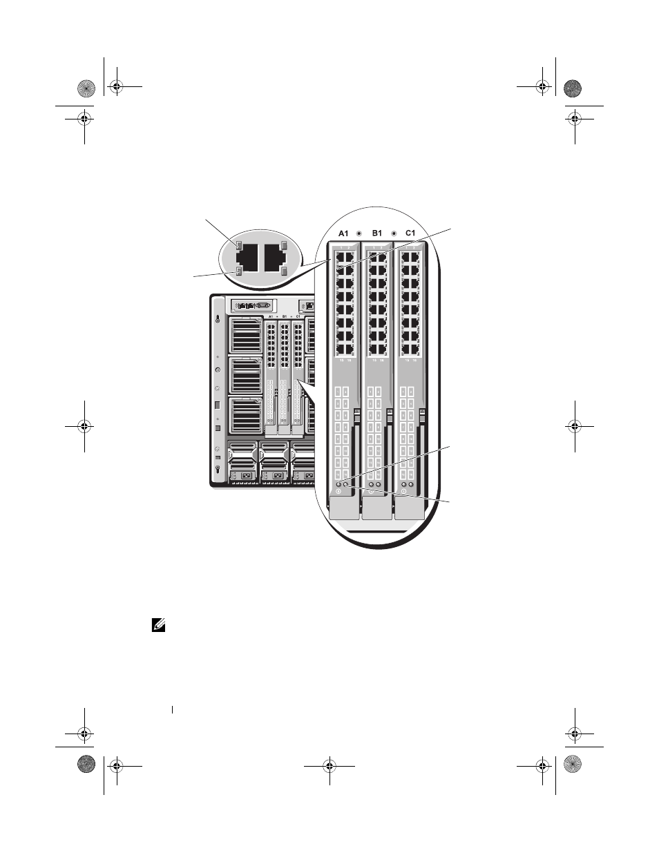
Figure 3-20. Ethernet Pass-Through Module
NOTE:
Connectors on the Ethernet pass-through module correspond directly to the
blade number. For example, blade 5 is connected to port 5 on the Ethernet pass-
through module. Integrated network adapter 1 maps to I/O slot A1. Integrated
network adapter 2 maps to I/O slot A2.
1
link indicator (16)
2
RJ45 Ethernet connector (16)
3
power indicator
4
status/identification indicator
5
activity indicator (16)
1
5
2
3
4
book.book Page 84 Wednesday, March 9, 2011 3:11 PM
See also other documents in the category Dell Computer Accessories:
- POWEREDGE 2950 (10 pages)
- POWEREDGE 2950 (15 pages)
- POWEREDGE 2950 (182 pages)
- POWEREDGE 2950 (112 pages)
- POWEREDGE 2950 (186 pages)
- Console Switch (58 pages)
- PowerConnect 2024 (46 pages)
- 2161DS-2 (56 pages)
- 5316M (15 pages)
- PowerConnect M6348 (737 pages)
- PRECISION 530 (8 pages)
- PRECISION 530 (126 pages)
- PRECISION 530 (300 pages)
- INFINISCALE III M2401G (27 pages)
- POWEREDGE RADI H700 (29 pages)
- ? PowerEdge 6800 (31 pages)
- POWEREDGE M1000E (2 pages)
- POWEREDGE M1000E (9 pages)
- POWEREDGE M1000E (54 pages)
- POWEREDGE M1000E (26 pages)
- POWEREDGE M1000E (130 pages)
- POWEREDGE M1000E (12 pages)
- POWEREDGE M1000E (310 pages)
- POWEREDGE M1000E (80 pages)
- POWEREDGE M1000E (586 pages)
- POWEREDGE M1000E (20 pages)
- POWEREDGE M1000E (64 pages)
- POWEREDGE M1000E (222 pages)
- POWEREDGE M1000E (302 pages)
- POWEREDGE M1000E (41 pages)
- POWEREDGE M1000E (34 pages)
- POWEREDGE M1000E (2 pages)
- POWEREDGE M1000E (72 pages)
- POWEREDGE M1000E (1168 pages)
- POWEREDGE M1000E (382 pages)
- POWEREDGE M1000E (1080 pages)
- POWEREDGE M1000E (370 pages)
- POWEREDGE M1000E (14 pages)
- POWEREDGE M1000E (116 pages)
- POWEREDGE M1000E (268 pages)
- POWEREDGE M1000E (2 pages)
- POWEREDGE M1000E (94 pages)
- POWEREDGE M1000E (260 pages)
- POWEREDGE M1000E (138 pages)