Basic operation of the computer – CatEye CC-TR200DW (V2c) User Manual
Page 8
ENG-15
ENG-14
ENG
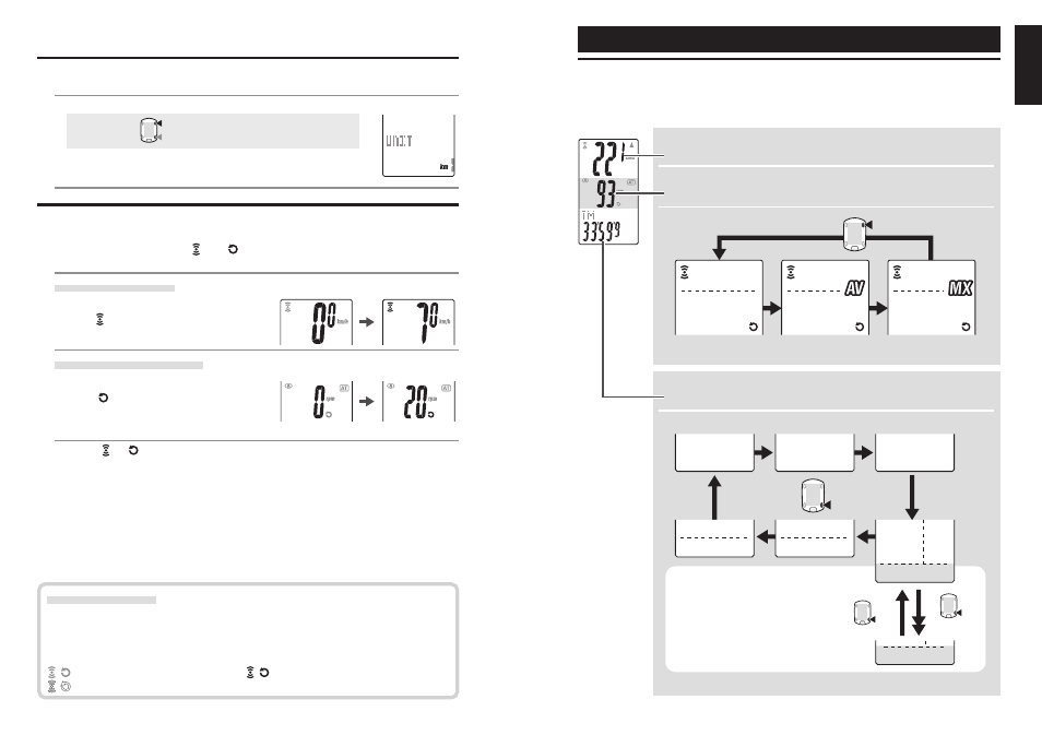
Average
speed
Average
cadence
Maximum
speed
Maximum
cadence
Current speed
Cadence
M1/+
M2/-
M2/-
M2/-
Date
Clock
Total time
Total distance
Elapsed time
Trip distance
Countdown
distance
Lap
number
Lap timer
Average
lap
speed
Lap distance
(2 Sec.)
5. Selecting speed unit
Select the speed unit from “km” and “mile”.
1. Select the speed unit.
km
↔
↔
↔
↔
↔ mile:
M1/+
M2/-
2. After selecting, press the MENU button. The measurement
screen appears and the computer set-up is completed.
6. Operation test
Test the functioning of the speed sensor (SPEED) and the cadence sensor (CADENCE).
* If the sensor signal icons, , and are turned off, press the M1/+ or M2/- button
to turn them on.
Speed sensor (SPEED)
1. Raise the rear wheel and spin the wheel.
2. When flashes on the computer screen and
the speed is displayed, it is operating normally.
Cadence sensor (CADENCE)
1. Turn the crank.
2. When flashes on the computer screen
and the cadence is displayed, it is
operating normally.
* When or does not flash, the position of the sensor and the magnet is not
proper. Check and adjust the position of the sensor and magnet again (page 7).
Important: In the following situations, it is possible that other sensor's ID was picked up;
(such can happen when performing ID Synch at the race venue or group rides)
• Does not display values, even though sensor/magnet position is proper
Recommended Action: Go to the computer's ID Synch setup screen
(page 23) and go through the process of ID Synch. (Make sure that here
is no similar devices in the vicinity. Signal transition distance can vary
from environmental conditions such as weather, buildings, etc)
Basic operation of the computer
Functions on the measurement screen
The measurement screen displays 4 different types of data, which are switched by press-
ing the M1/+ and M2/- buttons.
The display data are as follows.
Upper display data
Displays the data related to the speed.
Middle display data
Displays the data related to the cadence.
Lower display data
Displays the other data.
Real time lap data
(on-going lap data)
* Pressing and holding the M2/-
button while displaying the lap
timer switches the lap timer to the
lap distance. Pressing it again
returns to the lap timer.
* Upper and Middle display data are switched in sync together.
Switch using the M1/+ button
Switch using the M2/- button
(or)
Sensor signal status
If there is no incoming signal for approximately 5 minutes, the transmission stops
and no longer receive the sensor data. Once you press the M1/+ or M2/- button, the
computer will come out of the Sleep mode and return to the Stand-by for sensor
signal. Signal transmission status can be checked with Signal icon.
(flashing) : Receiving sensor signal
(constant) : Stand-by for sensor signal
(off) : Transmission off