Figure 1-5 – Dell POWERVAULT MD1000 User Manual
Page 13
About Your System
13
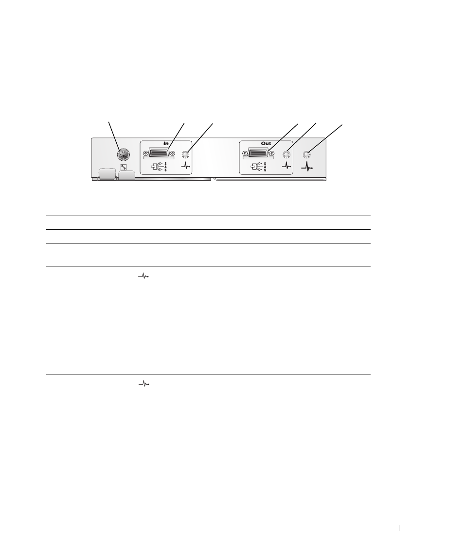
For a description of each component on the front panel of the EMM, see Table 1-4. For an explanation of
how to connect the enclosure using the EMM ports, see "Operating Your Storage Enclosure."
Figure 1-5. EMM External Panel
Table 1-4. EMM Component Functions
Item Component
Icon
Function
1
Debug Port
Dell factory use only.
2
SAS Port (In)
In
Provide SAS connection for cabling to host or next
upchain expansion enclosure (unified mode only).
3
In Port Link Status
LED (green/amber)
Green: All links into the port are connected.
Amber: One or more links into the port are not
connected.
Off: Interface is not active.
4
SAS Port (Out)
Out
Provide SAS connection for cabling to the next
downchain expansion enclosure in a daisy chain
(unified mode only).
NOTE:
The SAS Out port is disabled if the enclosure
is running split mode. For more information, see
"Operating Your Storage Enclosure."
5
Out Port Link
Status LED
(green/amber)
Green: All links out of the port are connected.
Amber: One or more links out of the port are not
connected.
Off: Interface is not active.
1
2
3
4
5
6