Table 4a — refrigerant piping sizes — 60 hz units, Table 5a — refrigerant piping sizes — 50 hz units, Fig. 4 — suction line piping 9 – Carrier 38AKS013-024 User Manual
Page 9
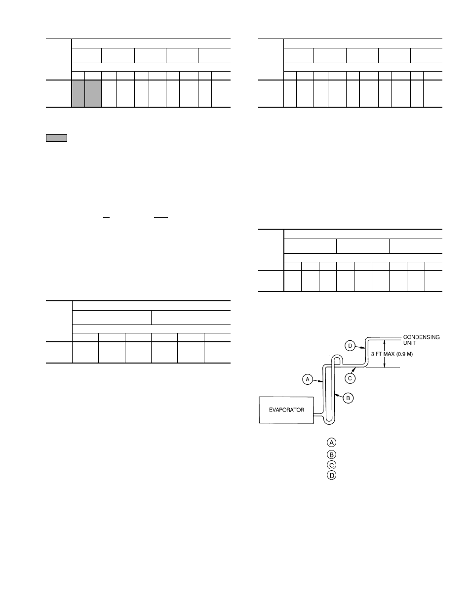
Table 4A — Refrigerant Piping Sizes — 60 Hz Units
UNIT
38AKS
LENGTH OF INTERCONNECTING PIPING, FT (M)
0-15
(0-4.5)
15-25
(4.5-7.5)
25-50
(7.5-15)
50-75
(15-23)
75-100
(23-30)
Line Size (in. OD)
L
S
L
S
L
S
L
S
L
S
013
1
⁄
2
1
1
⁄
8
1
⁄
2
1
1
⁄
8
5
⁄
8
1
3
⁄
8
5
⁄
8
1
3
⁄
8
5
⁄
8
1
5
⁄
8
*
014
1
⁄
2
1
1
⁄
8
1
⁄
2
1
3
⁄
8
5
⁄
8
1
3
⁄
8
5
⁄
8
1
5
⁄
8
*
7
⁄
8
1
5
⁄
8
*
016
1
⁄
2
1
3
⁄
8
5
⁄
8
1
3
⁄
8
5
⁄
8
1
5
⁄
8
7
⁄
8
1
5
⁄
8
7
⁄
8
2
1
⁄
8
*
024
5
⁄
8
1
5
⁄
8
5
⁄
8
1
5
⁄
8
7
⁄
8
1
5
⁄
8
7
⁄
8
2
1
⁄
8
7
⁄
8
2
1
⁄
8
LEGEND
L — Liquid
S — Suction
Close-coupled.
*Requires a double suction riser if 2 unloaders are used and the
evaporator is below the condensing unit. See Table 4B and Fig. 4
for more information.
NOTES:
1. Pipe sizes are based on a 2 F (1.1 C) loss for liquid lines and a
1.5 F (0.8 C) loss for suction lines.
2. Pipe sizes are based on an equivalent length equal to the maxi-
mum length of interconnecting piping plus 50% for fittings. A more
accurate estimate may result in smaller sizes.
3. Line size conversion to mm:
in.
mm
1
⁄
2
12.7
5
⁄
8
15.9
7
⁄
8
22.2
1
1
⁄
8
28.6
1
3
⁄
8
34.9
1
5
⁄
8
41.3
2
1
⁄
8
54.0
Table 4B — Refrigerant Piping Sizes,
Double Suction Risers — 60 Hz Units
UNIT
38AKS
LENGTH OF INTERCONNECTING PIPING, FT (M)
50-75
(15-23)
75-100
(23-30)
Line Size (in. OD)
A
B
C
A
B
C
013
—
—
—
1
1
⁄
8
1
3
⁄
8
1
5
⁄
8
014
1
1
⁄
8
1
3
⁄
8
1
5
⁄
8
1
1
⁄
8
1
3
⁄
8
1
5
⁄
8
016
—
—
—
1
3
⁄
8
1
5
⁄
8
2
1
⁄
8
NOTES:
1. See Fig. 4 for ‘‘A,’’ ‘‘B,’’ and ‘‘C’’ dimensions.
2. No double suction risers are needed for unit size 024.
3. See Table 4A for line size conversion to mm.
Table 5A — Refrigerant Piping Sizes — 50 Hz Units
COND
UNIT
38AKS
LENGTH OF INTERCONNECTING PIPING, FT (M)
0-15
(0-4.5)
15-25
(4.5-7.5)
25-50
(7.5-15)
50-75
(15-23)
75-100
(23-30)
Line Size (in. OD)
L
S
L
S
L
S
L
S
L
S
013
1
⁄
2
1
1
⁄
8
1
⁄
2
1
1
⁄
8
5
⁄
8
1
3
⁄
8
5
⁄
8
1
3
⁄
8
5
⁄
8
1
3
⁄
8
*
014
1
⁄
2
1
1
⁄
8
5
⁄
8
1
3
⁄
8
5
⁄
8
1
3
⁄
8
7
⁄
8
1
5
⁄
8
*
7
⁄
8
1
5
⁄
8
*
016
5
⁄
8
1
3
⁄
8
5
⁄
8
1
3
⁄
8
5
⁄
8
1
5
⁄
8
*
7
⁄
8
1
5
⁄
8
*
7
⁄
8
1
5
⁄
8
*
024
5
⁄
8
1
3
⁄
8
5
⁄
8
1
3
⁄
8
5
⁄
8
1
5
⁄
8
7
⁄
8
1
5
⁄
8
7
⁄
8
1
5
⁄
8
*Requires a double suction riser if 2 unloaders are used and the evapo-
rator is below the condensing unit. See Table 5B and Fig. 4 for more
information.
NOTES:
1. Pipe sizes are based on 2 F (1.1 C) max loss for liquid lines and
1.5 F (0.8 C) max loss for suction lines, selected at maximum length
for each interval and for matched systems at nominal rating con-
ditions, nominal airflow.
2. Pipe sizes are based on an equivalent length equal to the maxi-
mum length of interconnecting piping plus 50% for fittings. A more
accurate estimate may result in smaller sizes.
3. See Table 4A for line size conversion to mm.
Table 5B — Refrigerant Piping Sizes,
Double Suction Risers — 50 Hz Units
COND
UNIT
38AKS
LENGTH OF INTERCONNECTING PIPING FT (M)
25-50
(7.5-15)
50-75
(15-23)
75-100
(23-30)
Line Size (in. OD)
A
B
C
A
B
C
A
B
C
013
—
—
—
—
—
—
1
1
⁄
8
1
3
⁄
8
1
5
⁄
8
014
—
—
—
1
1
⁄
8
1
3
⁄
8
1
5
⁄
8
1
1
⁄
8
1
3
⁄
8
1
5
⁄
8
016
1
1
⁄
8
1
3
⁄
8
1
5
⁄
8
1
1
⁄
8
1
3
⁄
8
1
5
⁄
8
1
1
⁄
8
1
3
⁄
8
1
5
⁄
8
NOTES:
1. See Fig. 4 for ‘‘A,’’ ‘‘B,’’ and ‘‘C’’ dimensions.
2. Double suction risers are not required for unit size 024.
3. See Table 4A for line size conversion to mm.
LEGEND
Suction Riser
Without Trap
Suction Riser
With Trap
Suction Line to Condensing Unit
Short Vertical Riser Into
Condensing Unit:
38AKS013
— 1
1
⁄
8
in. OD
38AKS014,016 — 1
3
⁄
8
in. OD
38AKS024
— 1
5
⁄
8
in. OD
Fig. 4 — Suction Line Piping
9