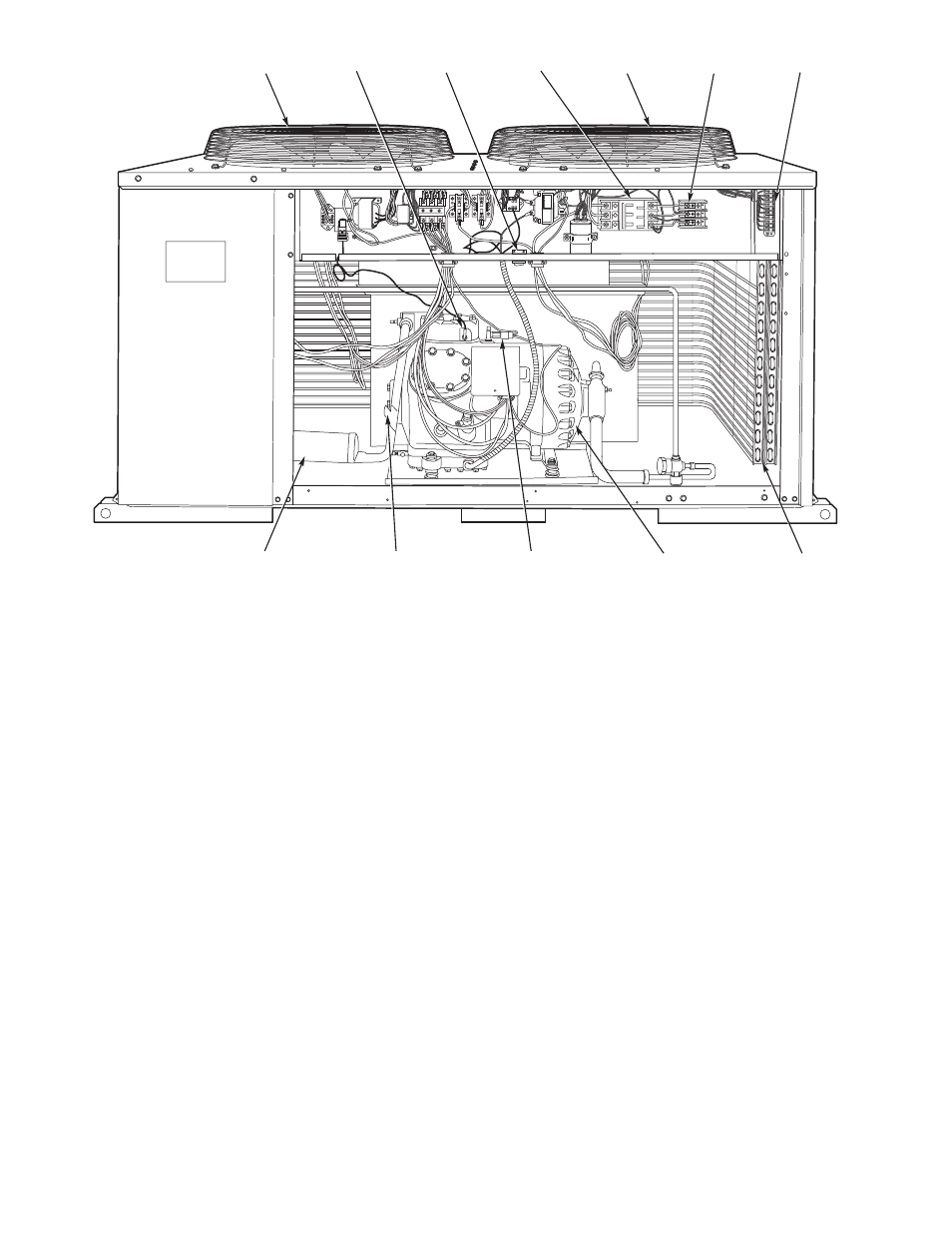
Fig. 2 — component locations (typical) 3 – Carrier 38AKS013-024 User Manual
Page 3
1
3
2
4
5
6
7
8
12
9
10
11
LEGEND
1 — No. 1 Fan
5 — No. 2 Fan
9 — Compressor
2 — High-Pressure Switch
6 — Terminal Block 1 (Unit Power)
10 — Low-Pressure Switch
3 — Circuit Breaker — Control Circuit
7 — Terminal Block 2 (Control Power)
11 — Hot Gas Bypass Piping Stub (
3
⁄
8
-in. ODM)
4 — Circuit Breakers — Power Circuits
8 — Wraparound Coil
12 — Muffler
Fig. 2 — Component Locations (Typical)
3
See also other documents in the category Carrier Conditioners:
- 42S (72 pages)
- 30GT (4 pages)
- 48SS060 (8 pages)
- 50ME (54 pages)
- 38AH024-034 (26 pages)
- ZC (28 pages)
- 30GA (12 pages)
- COMFORTLINK 48A2 (8 pages)
- 48HE003---006 (64 pages)
- 33ZCSECTRM (52 pages)
- 19XRV (40 pages)
- MODU-PAC 50DF (37 pages)
- 17DA (8 pages)
- SINGLE PACKAGED ELECTRIC COOLING UNITS 50GS (28 pages)
- 48JZ (N) 024-060 (30 pages)
- 30GX080-176 (8 pages)
- 50DL (24 pages)
- 50GL-A (4 pages)
- NP034-074 (72 pages)
- 40GXQ (12 pages)
- 30XA080-500 (8 pages)
- 39E (12 pages)
- 40KMQ------301 (10 pages)
- 38AE (12 pages)
- 48AW (118 pages)
- 38GXQ (28 pages)
- 48ES---A (38 pages)
- 48GL (22 pages)
- 48GH (22 pages)
- 40QA024-060 (24 pages)
- TJF004 (52 pages)
- 39LD (40 pages)
- 48DL (4 pages)
- 48/50TC04---28 (44 pages)
- 50EJ (56 pages)
- 17EX (120 pages)
- 50BA (24 pages)
- 50BB (16 pages)
- 50BB (8 pages)
- 50BJ (20 pages)
- 30H (16 pages)
- 48HJD005-007 (48 pages)
- 50ZP (6 pages)
- 50DP016 (16 pages)
- 50LJ008-014 (19 pages)