Figure 2-4 – Cabletron Systems HSIM-G01 User Manual
Page 22
Chapter 2: Installation
2-8
HSIM-G01/G09 User’s Guide
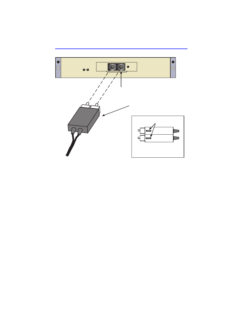
Figure 2-4
Fiber Connections
3.
At the other end of the fiber optic cable, attach the SC connector to the
other device.
4.
Verify that a link exists by checking that the link (LNK) LED is ON
(solid green), the port receive (RX) LED is ON (flashing amber,
blinking green, or solid green). Refer to
LEDs. If the RX LED is OFF and the transmit (TX) LED is not
blinking amber, perform the following steps until it is ON:
a.
Check that the power is turned on for the device at the other end of
the link.
b.
Verify proper crossover of fiber strands between the port on the
HSIM-G and the fiber optic device at the other end of the fiber
optic link segment.
c.
Verify that the fiber connection meets the dB loss specifications
outlined in
SC Connector
Key Latch (bottom of SC Connector)
(bottom view)
keys
SC Connector
HSIM-G
LNK
SX
- FOT-F3 (41 pages)
- FOT-F3 (44 pages)
- BRIM-F6 (41 pages)
- WPIM-RT1 (50 pages)
- BRIM-WT1 (32 pages)
- 36 (33 pages)
- 9T101-04 (28 pages)
- FDDI Repeater (29 pages)
- SWPIM-BRI (34 pages)
- 9C114 (26 pages)
- SMARTSWITCH ROUTER 9032578-05 (398 pages)
- HSIM-W6 (258 pages)
- NB25 E (30 pages)
- HSIM-FE6 (42 pages)
- Expansion module 9E429-36 (18 pages)
- EMM-E6 Ethernet (205 pages)
- Environmental Module TM 9C300-1 (50 pages)
- CSMIM-T1 (198 pages)
- NBR-620 (73 pages)
- E2100 (42 pages)
- KBU64 Rackmount (26 pages)
- AirConnect 3Com (93 pages)
- 802.1Q (92 pages)
- W85 (60 pages)
- ELS10-26 (170 pages)
- Expansion module 9E106-06 (40 pages)
- 6H259-17 (58 pages)
- Expansion module 9F120-08 (12 pages)
- EMC39-12 (33 pages)
- 6A000/ZX-250 (268 pages)
- Expansion module DELHE-UA (50 pages)
- Expansion module 9T122-08 (36 pages)
- DMS-100 (196 pages)
- BRIM E100 BRIM-E100 (42 pages)
- Cabletron CyberSWITCH CSX400 (275 pages)
- Cabletron SmartSwitch Router 250 (34 pages)
- Network Router (100 pages)
- 9W111-08 (28 pages)
- CSX400 (101 pages)
- Cabletron SmartSwitch Router 510 (106 pages)
- SEHI-32/34 (90 pages)
- SmartSwitch (338 pages)
- 9T106-01 (28 pages)
- Switch 9H531-17 (38 pages)