Package diagrams – Cypress CY7C107BN User Manual
Page 6
CY7C107BN
CY7C1007BN
Document #: 001-06426 Rev. **
Page 6 of 7
© Cypress Semiconductor Corporation, 2006. The information contained herein is subject to change without notice. Cypress Semiconductor Corporation assumes no responsibility for the use
of any circuitry other than circuitry embodied in a Cypress product. Nor does it convey or imply any license under patent or other rights. Cypress products are not warranted nor intended to be
used for medical, life support, life saving, critical control or safety applications, unless pursuant to an express written agreement with Cypress. Furthermore, Cypress does not authorize its
products for use as critical components in life-support systems where a malfunction or failure may reasonably be expected to result in significant injury to the user. The inclusion of Cypress
products in life-support systems application implies that the manufacturer assumes all risk of such use and in doing so indemnifies Cypress against all charges.
All product or company names mentioned in this document may be the trademarks of their respective holders.
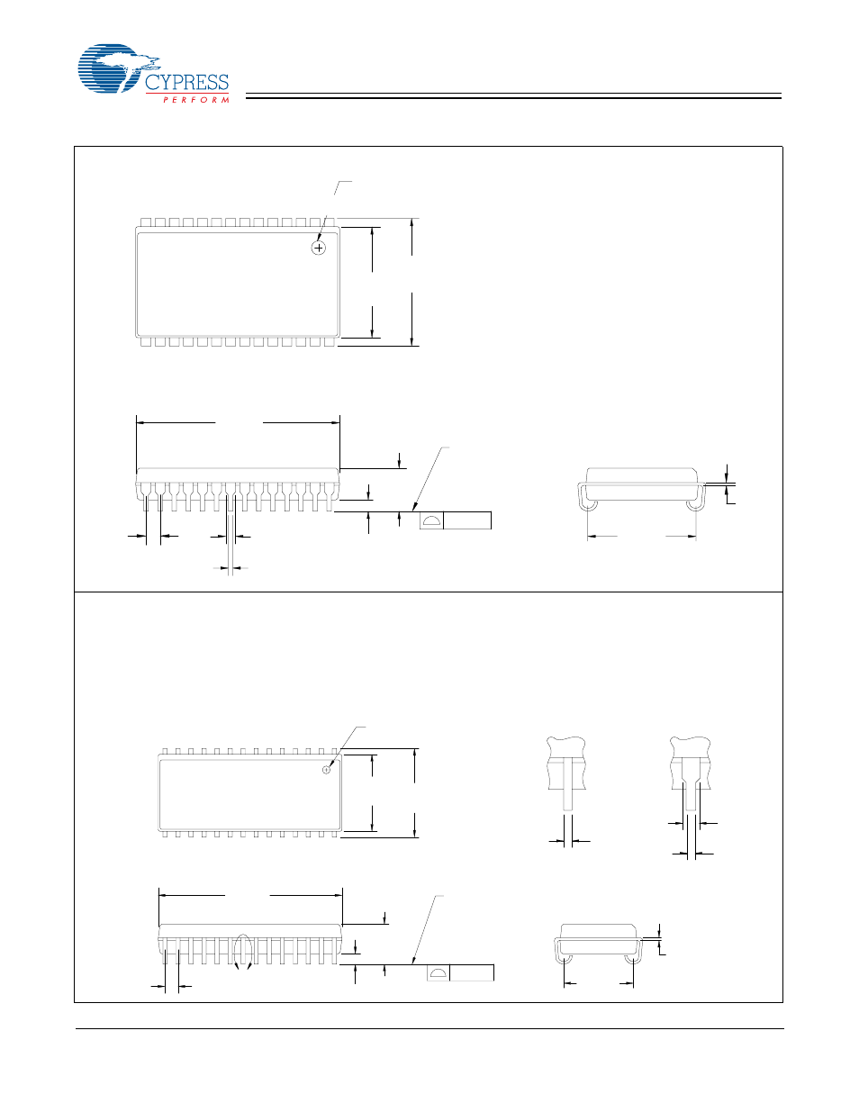
Package Diagrams
51-85032-*B
PIN 1 I.D
.435
.395
.445
.405
.128
.148
.360
.380
.026
.015
.032
.020
DIMENSIONS IN INCHES
MIN.
MAX.
.025 MIN.
.007
.013
.050
TYP.
.720
.730
1
14
15
28
0.004
SEATING PLANE
51-85032.*B
28-Lead (400-Mil) Molded SOJ (51-85032)
MIN.
MAX.
PIN 1 ID
0.291
0.300
0.050
TYP.
0.007
0.013
0.330
0.350
0.120
0.140
0.025 MIN.
0.262
0.272
0.697
0.713
0.013
0.019
0.014
0.020
0.032
0.026
A
A
DETAIL
EXTERNAL LEAD DESIGN
OPTION 1
OPTION 2
1
14
15
28
0.004
SEATING PLANE
NOTE :
1. JEDEC STD REF MO088
2. BODY LENGTH DIMENSION DOES NOT INCLUDE MOLD PROTRUSION/END FLASH
MOLD PROTRUSION/END FLASH SHALL NOT EXCEED 0.006 in (0.152 mm) PER SIDE
3. DIMENSIONS IN INCHES
51-85031-*C
28-Lead (300-Mil) Molded SOJ (51-85031)