Basic installation instructions, Maintenance instructions 2, Guidelines – Ames Fire & Waterworks LFM300, LFM300N Lead Free Double Check Detector Assemblies User Manual
Page 2: Instructions
2
Basic Installation Instructions
Guidelines
Most field problems occur because dirt and debris present in the system at the time
of installation becomes trapped in the check valves.
The system should be flushed
before the valve is installed. If the system is not flushed until after the valve is installed,
remove both check modules from the valve and open the inlet shutoff to allow water
to flow for a sufficient time to flush debris from the water line. If debris in the water
system continues to cause fouling, a strainer can be installed upstream of the backflow
assembly.
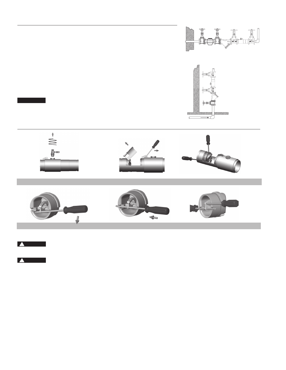
The Series M200 and M300 may be installed in either horizontal or vertical position
as long as the backflow assembly is installed in accordance with the direction of the
flow arrow on the assembly and the local water authority approves the installation.
The assembly should be installed with adequate clearance around the valve to allow
for inspection, testing and servicing. 12" (300mm) should be the minimum clearance
between the lower portion of the assembly and the floor or grade.
NOTICE
Assembly body should not be painted.
Horizontal Installation
Vertical
Installation
Figure D
Figure E
Figure F
Figure A
Figure B
Figure C
WARNING
!
Prior to servicing any Ames valve, it is mandatory to shut down the
water system by closing both the inlet and outlet shutoff valves.
WARNING
!
While the spring mechanism is removed for check
servicing, never pull the screwdriver out or off the support notches
on the arbors. Doing so may cause bodily injuries. Keep fingers out
of seat and clapper area.
After shutoff valves are closed, open test cock #2, #3 & #4 to re-
lieve pressure within the backflow assembly.(Figure C on page 4.)
1. After #3 test cock has been opened to relieve pressure, remove
#3 test cock from housing. (Figure A)
2. Insert a #3 screwdriver through the hole on the top of the cover
sleeve and using both hands rotate the cover sleeve approxi-
mately
1
⁄
4
-turn clockwise and
1
⁄
4
-turn counterclockwise to break
the sleeve O-ring seals. Using the screwdriver, slowly slide the
cover sleeve to the downstream side of the housing. (Figure B)
3. Remove the stainless steel check retainer from the housing.
(Figure B)
4. Remove the #1 check module (Figure C) by inserting two flat
blade screwdrivers into the slots on either side of the check
module and gently pry the check module toward the open zone.
5. Remove #2 check module with the same instructions as in
#4 above. For servicing 6" checks see 8" – 10" instructions on
page 3.
6. To clean or inspect either check module, insert a #3 screwdriver
through the downstream side of the check module as shown in
Figure D & E. When the screwdriver is in place, remove the “E”-
clip (Figure F) and pin connecting the structural members and the
check clapper will open with no tension.
7. Thoroughly clean the seating area. The sealing disc may be
removed, if necessary, by removing the screws connecting the
keeper plate to the clapper. The sealing disc may be reversed
and reinstalled if the elastomer is cut or damaged.
8. Wash check module and O-ring and inspect for any damage. If
damaged, reinstall new parts.
9. After thorough cleaning, lubricate O-ring w/FDA approved lu-
bricant, replace pin and “E”-clip in structural members, remove
screw driver and reinstall check modules and assemble housing
in reverse order of these instructions.
Maintenance Instructions 2
1
/
2
" – 4"
Instructions