Carrier 48TF004-007 User Manual
Page 5
5
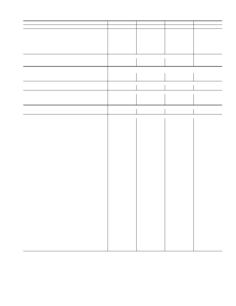
Table 1 — Physical Data — 48TF004-007
LEGEND
*Evaporator coil fin material/condenser coil fin material. Contact your local
representative for details about coated fins.
†Weight of 14-in. roof curb.
**Single phase/three-phase.
††Rollout switch lockout is manually reset by interrupting power to unit or
resetting thermostat.
|| Single-phase units have a single-stage gas valve. The heating input values
are as follows:
48TFF004, 115,000 Btuh
48TFF005, 150,000 Btuh
48TFF006, 150,000 Btuh
NOTE: High-static motor not available on single-phase units.
UNIT SIZE 48TF
E/F/M/N004
D/E/F/L/M/N005
D/E/F/L/M/N006
D/E/F007
NOMINAL CAPACITY (tons)
3
4
5
6
OPERATING WEIGHT (lb)
Unit
Al/Al*
460
470
490
565
Al/Cu*
465
476
497
576
Cu/Cu*
468
482
505
587
Economizer
Durablade
34
34
34
34
EconoMi$er
47
47
47
47
Roof Curb†
115
115
115
115
COMPRESSOR
Reciprocating
Scroll
Quantity
1
1
1
1
No. Cylinders (per Circuit)
2
2
2
2
Oil (oz)
50
50
50
54
REFRIGERANT TYPE
R-22
Expansion Device
Acutrol™ Metering Device
Operating Charge (lb-oz)
Circuit 1
4-4
6-6
6-14
9-0
Circuit 2
—
—
—
—
CONDENSER COIL
Enhanced Copper Tubes, Aluminum Lanced Fins
Rows...Fins/in.
1...17
2...17
2...17
2...17
Total Face Area (sq ft)
8.36
8.36
10.42
10.42
CONDENSER FAN
Propeller Type
Nominal Cfm
3500
4000
4000
4000
Quantity...Diameter (in.)
1...22.0
1...22.0
1...22.0
1...22.0
Motor Hp...Rpm
1
/
4
...1100
1
/
4
...1100
1
/
4
...1100
1
/
4
...1100
Watts Input (Total)
325
325
325
325
EVAPORATOR COIL
Enhanced Copper Tubes, Aluminum Double-Wavy Fins
Rows...Fins/in.
2...15
2...15
3...15
4...15
Total Face Area (sq ft)
4.17
5.5
5.5
5.5
EVAPORATOR FAN
Centrifugal Type
Quantity...Size (in.)
Std
1...10 x 10
1...10 x 10
1...11 x 10
1...10 x 10
Alt
1...10 x 10
1...10 x 10
1...10 x 10
—
High-Static
1...10 x 10
1...10 x 10
1...11 x 10
1...10 x 10
Type Drive
Std
Direct
Direct
Direct
Belt
Alt
Belt
Belt
Belt
—
High-Static
Belt
Belt
Belt
Belt
Nominal Cfm
1200
1600
2000
2400
Maximum Continuous Bhp
Std
.34
.75
1.20
2.40
Alt
1.00
1.00
1.30/2.40**
—
High-Static
2.40
2.40
2.90
2.90
Motor Frame Size
Std
48
48
48
56
Alt
48
48
56
—
High-Static
56
56
56
56
Nominal Rpm High/Low
Std
860/800
1075/970
1075/970
—
Alt
1620
1620
1725
—
High-Static
1725
1725
1725
1725
Fan Rpm Range
Std
—
—
—
1070-1460
Alt
760-1000
835-1185
900-1300
—
High-Static
1075-1455
1075-1455
1300-1685
1300-1685
Motor Bearing Type
Ball
Ball
Ball
Ball
Maximum Allowable Rpm
2100
2100
2100
2100
Motor Pulley Pitch Diameter Min/Max (in.)
Std
—
—
—
2.8/3.8
Alt
1.9/2.9
1.9/2.9
2.4/3.4
—
High-Static
2.8/3.8
2.8/3.8
3.4/4.4
3.4/4.4
Nominal Motor Shaft Diameter (in.)
Std
1
/
2
1
/
2
1
/
2
5
/
8
Alt
1
/
2
1
/
2
5
/
8
—
High-Static
5
/
8
5
/
8
5
/
8
5
/
8
Fan Pulley Pitch Diameter (in.)
Std
—
—
—
4.5
Alt
4.5
4.0
4.5
—
High-Static
4.5
4.5
4.5
4.5
Belt, Quantity...Type...Length (in.)
Std
—
—
—
1...A...40
Alt
1...A...34
1...A...34
1...A...39
—
High-Static
1...A...39
1...A...39
1...A...40
1...A...40
Pulley Center Line Distance (in.)
Std
—
—
—
14.7-15.5
Alt
10.0-12.4
10.0-12.4
14.7-15.5
—
High-Static
10.0-12.4
10.0-12.4
14.7-15.5
14.7-15.5
Speed Change per Full Turn of
Std
—
—
—
80
Movable Pulley Flange (rpm)
Alt
48
70
80
—
High-Static
65
65
60
60
Movable Pulley Maximum Full Turns
Std
—
—
—
5
From Closed Position
Alt
5
5
5
—
High-Static
6
6
5
5
Factory Setting
Std
—
—
—
3
Alt
3
3
3
—
High-Static
3
1
/
2
3
1
/
2
3
1
/
2
3
1
/
2
Factory Speed Setting (rpm)
Std
—
—
—
1225
Alt
856
975
1060
—
High-Static
1233
1233
1396
1396
Fan Shaft Diameter at Pulley (in.)
5
/
8
5
/
8
5
/
8
5
/
8
Al
—
Aluminum
Bhp —
Brake Horsepower
Cu
—
Copper