Baumer FHDx14 IO User Manual
Page 8
en_BA_FNDx14_FHDx14_IO.doc
8/14
Baumer Electric AG
12.04.2013/hem
Frauenfeld, Switzerland
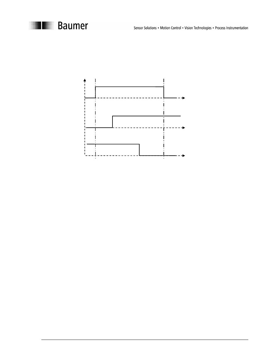
itself. Both teach-in parameters must be within the adjustable sensing distance and be more than 4%
of the sensing distance apart. The switching function (light/dark switching) is defined by the order of
the teach-in parameters (A/B).
Figure 2: Possible switching curves
5.1.3.1 Sample numerical teach-in:
1) A switching point is set at 150 mm (A) (Calibration curve 2).
Point A absolute in mm:
150 mm
→
0096 hex (= Switching point A)
Point B absolute in mm:
not valid
→
FFFF hex (= Switching point B)
Parameter to be written:
Switching points work:
0096FFFF hex
Save parameters to save the values permanently!
2) The sensing range is set inversely at 200 mm (B) (Calibration curve 3).
Point A absolute in mm:
not valid
→
FFFF hex (= Switching point A)
Point B absolute in mm:
200
→
00C8 hex
(= Switching point B)
Parameter to be written:
Switching points work:
FFFF00C8 hex
Save parameters to save the values permanently!
0
0
0
1
1
1
Switching bit/Switching output
A
B
A
B
Adjustable sensing
distance
(Calibration curve 1)
Taught-in sensing range
(Calibration curve 2)
Inverted sensing range
(Calibration curve 3)
50mm
400mm