Throw for standard diffusers – Carrier MODULINE 37HS User Manual
Page 82
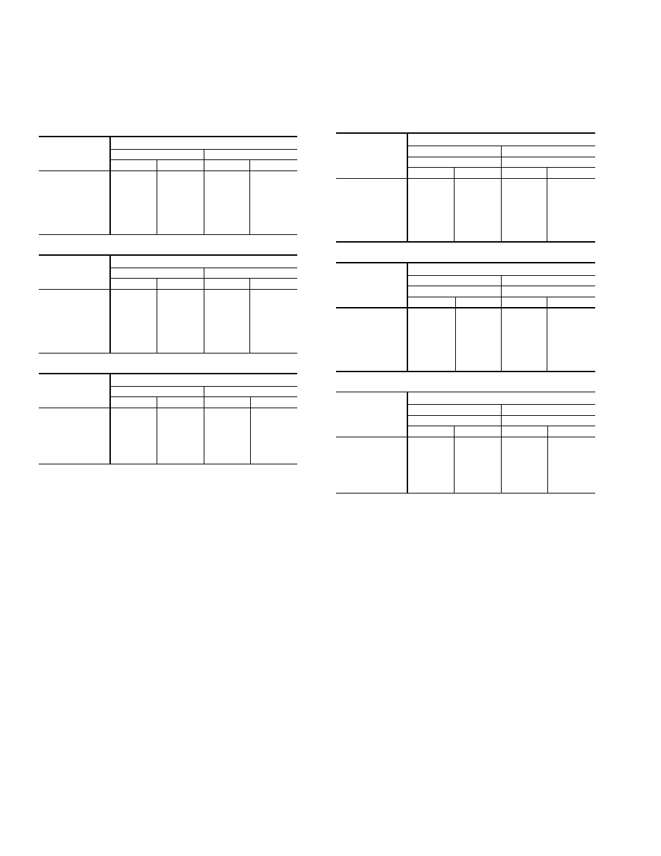
Throw for Standard Diffusers —
Tables 24 and 25
provide the suggested minimum and maximum coverages
the Moduline® air terminals can handle in a typical instal-
lation while maintaining the desired room conditions.
Table 24 — Air Throw Data —
1-Way and 2-Way Blow, 2-Slot Diffusers
37HS1 UNIT
AIRFLOW
(Cfm)
OPTIMUM AIR THROW (ft)
1-Way Blow
2-Way Blow
Min
Max
Min
Max
40
2.0
7.0
2.0
5.0
50
4.0
9.0
3.0
6.0
60
7.5
12.0
3.5
7.5
70
8.0
15.0
4.0
9.0
80
9.0
18.0
4.5
10.5
90
10.0
20.0
5.0
11.5
100
11.0
22.0
6.0
13.0
110
12.0
24.0
7.0
15.0
37HS2 UNIT
AIRFLOW
(Cfm)
OPTIMUM AIR THROW (ft)
1-Way Blow
2-Way Blow
Min
Max
Min
Max
80
2.0
7.0
2.0
5.0
100
4.0
9.0
3.0
6.0
120
7.5
12.0
3.5
7.5
140
8.0
15.0
4.0
9.0
160
9.0
18.0
4.5
10.5
180
10.0
20.0
5.0
11.5
200
11.0
22.0
6.0
13.0
220
12.0
24.0
7.0
15.0
37HS4 UNIT
AIRFLOW
(Cfm)
OPTIMUM AIR THROW (ft)
1-Way Blow
2-Way Blow
Min
Max
Min
Max
160
8.5
16.0
5.0
7.0
200
10.0
20.0
6.0
10.0
250
11.0
21.0
7.0
13.0
300
12.0
22.0
8.0
17.0
350
14.0
23.0
9.0
19.0
400
15.0
25.0
10.0
21.0
440
17.0
29.0
13.0
24.0
NOTES:
1. Minimum air throw refers to the distance from the diffuser where the air ve-
locity is 150 fpm. In maximum air throw, this velocity has dropped to 50 fpm.
2. Data is based on an area with a 9-ft ceiling. For higher ceilings, values may
be reduced by one foot for each foot of height increase. For specific instal-
lations, minimum values can be reduced if properly qualified. Values are
dependent on cfm only and are not affected by duct pressure.
The optimum air throw values given in the table are dis-
tances from the unit centerline to the outside wall or nearest
obstruction (wall, light fixture or opposing air stream).
Table 25 — Air Throw Data —
2-Way and 1-Way Director, 3-Slot Diffusers
37HS1 UNIT
AIRFLOW
(Cfm)
OPTIMUM AIR THROW (ft)
Heating
Cooling
1-Way Blow
2-Way Blow
Min
Max
Min
Max
40
2.0
7.0
2.0
5.0
50
4.0
9.0
3.0
6.0
60
7.5
12.0
3.5
7.5
70
8.0
15.0
4.0
9.0
80
9.0
18.0
4.5
10.5
90
10.0
20.0
5.0
11.5
100
11.0
22.0
6.0
13.0
110
12.0
24.0
7.0
15.0
37HS2 UNIT
AIRFLOW
(Cfm)
OPTIMUM AIR THROW (ft)
Heating
Cooling
1-Way Blow
2-Way Blow
Min
Max
Min
Max
80
2.0
7.0
2.0
5.0
100
4.0
9.0
3.0
6.0
120
7.5
12.0
3.5
7.5
140
8.0
15.0
4.0
9.0
160
9.0
18.0
4.5
10.5
180
10.0
20.0
5.0
11.5
200
11.0
22.0
6.0
13.0
220
12.0
24.0
7.0
15.0
37HS4 UNIT
AIRFLOW
(Cfm)
OPTIMUM AIR THROW (ft)
Heating
Cooling
1-Way Blow
2-Way Blow
Min
Max
Min
Max
160
8.5
16.0
5.0
7.0
200
10.0
20.0
6.0
10.0
250
11.0
21.0
7.0
13.0
300
12.0
22.0
8.0
17.0
350
14.0
23.0
9.0
19.0
400
15.0
25.0
10.0
21.0
440
17.0
29.0
13.0
24.0
82