Fig. 16 — locate units to prevent down-drafts 26 – Carrier MODULINE 37HS User Manual
Page 26
EVALUATE THE THROW OF MODULINE
UNITS IN
POSSIBLE LOCATIONS — Check minimum throw for
2-way blow diffuser near walls and all one-way blow
diffusers.
Exceeding maximum throw is almost never a problem. A
2-way blow unit covers 50 ft at nominal cfm.
In perimeter rooms, if 2-way blow units are off center,
favor the exterior wall if possible.
Generally, one-way blow diffusers should blow away from
the nearest wall.
Air throw data in Tables 4 and 5 for the Moduline
air
terminals provides the suggested minimum and maximum
coverages the units can handle in a typical installation while
maintaining the desired room conditions.
The optimum air throw values given in the table are dis-
tances from the unit centerline to the outside wall or nearest
obstruction (wall, light fixture, or opposing air stream).
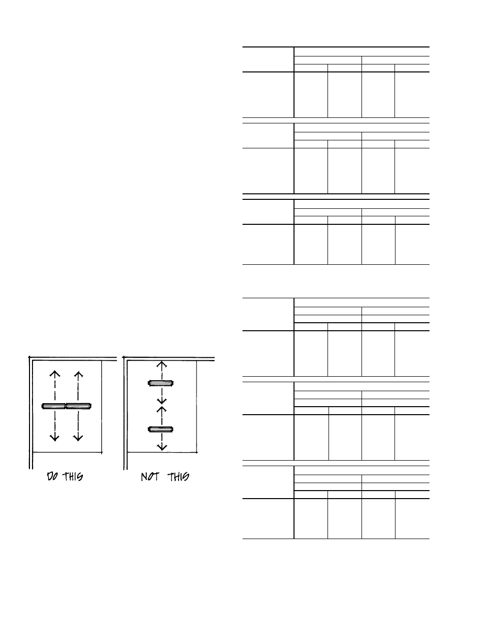
When given a choice, always put diffusers in line with each
other, not blowing at each other. If diffusers must be placed
so they are blowing at each other, the minimum throw must
be checked. Do not put units closer together than minimum
allows. Down-drafts caused by going below minimum will
bother room occupants. (Fig. 16)
Moduline
units can be placed fairly close to a wall or
partition. This is because the down-draft follows the wall
(stays close to the wall) and doesn’t bother the room occu-
pant. If furniture is placed against the wall near a Moduline
unit, it causes the air to be deflected causing drafts. The prob-
lem can often be solved by moving the furniture 6 in. or so
away from the wall.
Table 4 — Air Throw Data —
1-Way and 2-Way Blow, 2-Slot Diffusers
37HS1 UNIT
AIRFLOW
(Cfm)
OPTIMUM AIR THROW (ft)
1-Way Blow
2-Way Blow
Min
Max
Min
Max
40
2.0
7.0
2.0
5.0
50
4.0
9.0
3.0
6.0
60
7.5
12.0
3.5
7.5
70
8.0
15.0
4.0
9.0
80
9.0
18.0
4.5
10.5
90
10.0
20.0
5.0
11.5
100
11.0
22.0
6.0
13.0
110
12.0
24.0
7.0
15.0
37HS2 UNIT
AIRFLOW
(Cfm)
OPTIMUM AIR THROW (ft)
1-Way Blow
2-Way Blow
Min
Max
Min
Max
80
2.0
7.0
2.0
5.0
100
4.0
9.0
3.0
6.0
120
7.5
12.0
3.5
7.5
140
8.0
15.0
4.0
9.0
160
9.0
18.0
4.5
10.5
180
10.0
20.0
5.0
11.5
200
11.0
22.0
6.0
13.0
220
12.0
24.0
7.0
15.0
37HS4 UNIT
AIRFLOW
(Cfm)
OPTIMUM AIR THROW (ft)
1-Way Blow
2-Way Blow
Min
Max
Min
Max
160
8.5
16.0
5.0
7.0
200
10.0
20.0
6.0
10.0
250
11.0
21.0
7.0
13.0
300
12.0
22.0
8.0
17.0
350
14.0
23.0
9.0
19.0
400
15.0
25.0
10.0
21.0
440
17.0
29.0
13.0
24.0
Table 5 — Air Throw Data —
2-Way and 1-Way Director, 3-Slot Diffusers
37HS1 UNIT
AIRFLOW
(Cfm)
OPTIMUM AIR THROW (ft)
Heating
Cooling
1-Way Blow
2-Way Blow
Min
Max
Min
Max
40
2.0
7.0
2.0
5.0
50
4.0
9.0
3.0
6.0
60
7.5
12.0
3.5
7.5
70
8.0
15.0
4.0
9.0
80
9.0
18.0
4.5
10.5
90
10.0
20.0
5.0
11.5
100
11.0
22.0
6.0
13.0
110
12.0
24.0
7.0
15.0
37HS2 UNIT
AIRFLOW
(Cfm)
OPTIMUM AIR THROW (ft)
Heating
Cooling
1-Way Blow
2-Way Blow
Min
Max
Min
Max
80
2.0
7.0
2.0
5.0
100
4.0
9.0
3.0
6.0
120
7.5
12.0
3.5
7.5
140
8.0
15.0
4.0
9.0
160
9.0
18.0
4.5
10.5
180
10.0
20.0
5.0
11.5
200
11.0
22.0
6.0
13.0
220
12.0
24.0
7.0
15.0
37HS4 UNIT
AIRFLOW
(Cfm)
OPTIMUM AIR THROW (ft)
Heating
Cooling
1-Way Blow
2-Way Blow
Min
Max
Min
Max
160
8.5
16.0
5.0
7.0
200
10.0
20.0
6.0
10.0
250
11.0
21.0
7.0
13.0
300
12.0
22.0
8.0
17.0
350
14.0
23.0
9.0
19.0
400
15.0
25.0
10.0
21.0
440
17.0
29.0
13.0
24.0
NOTES:
1. Minimum air throw refers to the distance from the diffuser where the air ve-
locity is 150 fpm. In maximum air throw, this velocity has dropped to 50 rpm.
2. Data is based on an area with a 9-ft ceiling. For higher ceilings, values may
be reduced by one foot for each foot of height increase. For specific instal-
lations, minimum values can be reduced if properly qualified. Values are
dependent on cfm only and are not affected by duct pressure.
Fig. 16 — Locate Units to Prevent Down-Drafts
26