Carrier MODULINE 37HS User Manual
Page 70
VAV COOLING WITH PNEUMATIC WARM-UP OR FIRE
SAFETY SWITCH — Through the use of a specific pneu-
matic switch, the functions of pneumatic warm-up and fire
safety can be added to Moduline
installations.
Pneumatic warm-up offers an opportunity to open all Modu-
line units in an area to allow immediate hot air distribution
prior to the building occupancy. Through the use of a sepa-
rate pneumatic signal, the pneumatic warm-up switch, placed
in-line between the Moduline volume controller and the dif-
fuser or wall system powered thermostat, closes the low pres-
sure bleed in the thermostat line (in the same way as the
system powered warm-up switch). This raises the low side
pressure, opens the volume controller bleed and lowers the
bellows pressure, allowing airflow from the Moduline ter-
minal at the setting of the volume controller.
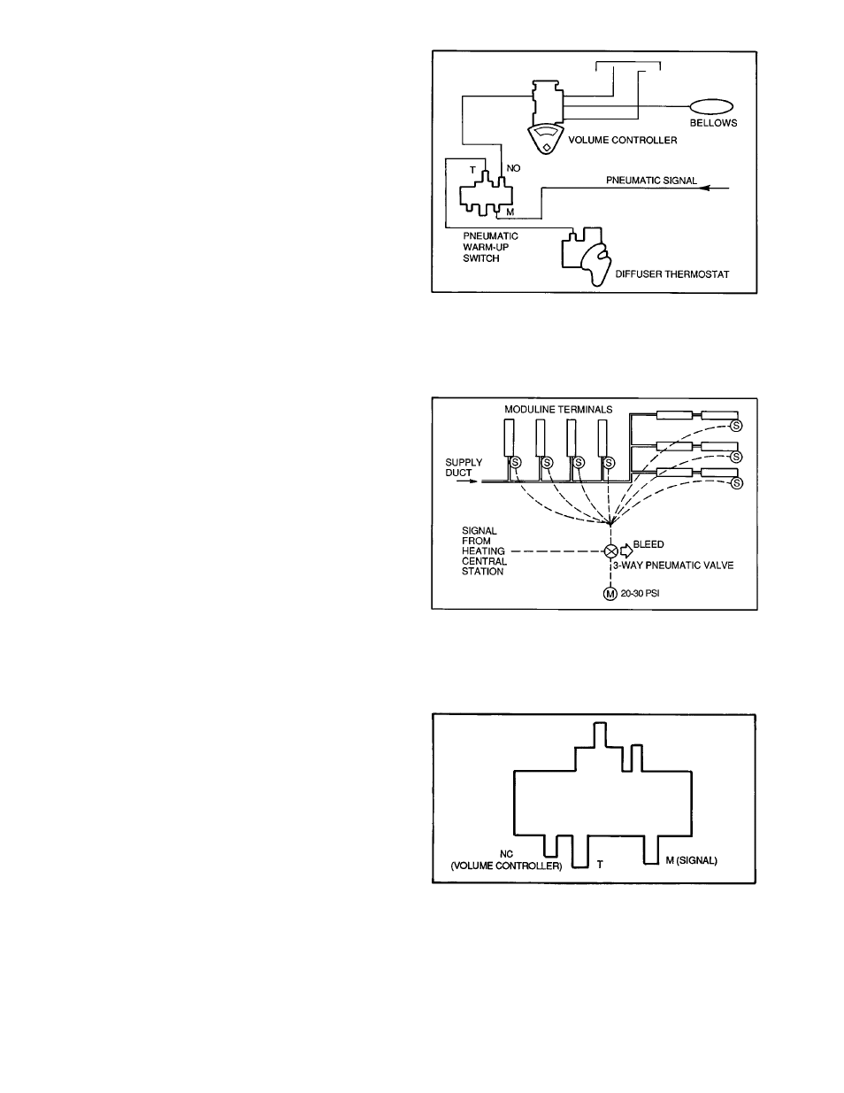
The pneumatic warm-up switch can be piped either NO or
NC. Figure 79 shows an NO arrangement. The switch is non-
adjustable and preset to close at 8 ± 2.0 psig. Thus a signal
pressure in excess of 10 psi will cause the switch to close.
A pneumatic warm-up switch is required for each Moduline
unit but only one pneumatic signal valve is required for mul-
tiple Moduline units. Figure 80 shows the basic piping.
The field-supplied 3-way pneumatic valve is supplied with
main pressure and is closed in cooling operation. When heat
for warm-up is required, a signal sent from the heat source
opens the pneumatic valve, supplying main pressure to the
Moduline pneumatic warm-up switches. When the heat is
discontinued, the pneumatic valve opens and the switches
return to an open configuration.
Note that the pneumatic warm-up switch is a nonbleed
device. The pneumatic valve should therefore be a 3-way
device, arranged to bleed out the pneumatic circuit down-
stream of the valve when the valve is closed.
The pneumatic warm-up switch can be arranged as an NC
device; Fig. 81 gives the piping connections.
For fire safety, the same switch is added to the Moduline
control circuit as a normally open fire safety switch as shown
in Fig. 82A. The fire safety switch on each Moduline ter-
minal is connected to a pneumatic distribution circuit on each
floor of the building. A 3-way valve is connected to the switches
and to the fire master control as shown in Fig. 83.
The operation is identical to the pneumatic warm-up cir-
cuit. At the onset of a fire, the fire master control opens the
Moduline units on the non-fire floors by closing the Modu-
line fire safety switches, raising the controller low side pres-
sure and bleeding the bellows. The 3-way pneumatic valve
on each floor supplies pneumatic pressure in excess of the
set point of 8.0 ± 2 psig. On the fire floor where air is to be
shut down, the distribution system uses a duct fire-damper
to stop the air, and the fire safety switch position is not the
determining factor in the Moduline operation.
If a normally closed fire switch is required, see piping dia-
gram shown in Fig. 82B. In this case, pneumatic pressure is
maintained on the fire switch when the system fan is acti-
vated. Loss of pneumatic pressure closes the fire switch, bleed-
ing the bellows.
LEGEND FOR FIG. 79 - 83
HW — Hot Water
NO — Normally Open
M
— Main
S
— Switch
NC
— Normally Closed
T
— Thermostat
Fig. 79 — Piping Diagram, NO Configuration,
Pneumatic Warm-Up
Fig. 80 — Basic Piping for Pneumatic
Warm-Up Switch
Fig. 81 — Piping Diagram, NC Configuration,
Pneumatic Warm-Up
70