Insulation, Minimum fluid loop volume – Carrier EVERGREEN 23XRV User Manual
Page 23
23
Insulation
23XRV MINIMUM FIELD-INSTALLED INSULATION
REQUIREMENTS
Factory insulation — Thermal insulation is factory-
provided to the following areas:
• Cooler (not including waterbox)
• Suction line
• Compressor and motor
• Oil cooling line and oil return system line (oil and refrig-
erant lines at or near evaporator pressure are insulated)
• VFD cooling line (oil and refrigerant lines at or near
evaporator pressure are insulated)
• Motor cooling line
• Vaporizer
• Liquid line and discharge line
• Float chamber
• Optional economizer (including vent line and econo-
mizer muffler)
Factory insulation is not available for the waterboxes.
Insulation applied at the factory is
1
/
2
-in. (13 mm) thick
closed cell and
1
/
2
-in. (13 mm) open cell PVC-Nitrile foam.
Some parts of the chiller are also treated with an outer
layer of
3
/
16
-in. (5 mm) thick vinyl. The
1
/
2
-in. (13 mm)
closed cell foam has a thermal conductivity K value of
0.28 (BTU in.)/(hr sqft °F) [0.0404 W/(m °C)] and
conforms with Underwriters Laboratories (UL) Standard
94, Classification 94 HF-1. Both the
1
/
2
-in. foam and the
3
/
16
-in. vinyl layer will pass flammability test method
MVSS 302.
Field insulation — As indicated in the Condensation vs
Relative Humidity table, the factory insulation provides
excellent protection against condensation under most op-
erating conditions. If temperatures in the equipment area
exceed the maximum design conditions, extra insulation is
recommended.
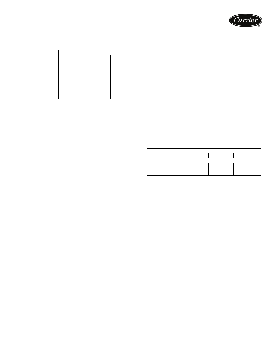
If the machine is to be field insulated, obtain the approx-
imate areas from the 23XRV Minimum Field-Installed Insu-
lation Requirements table.
Insulation of waterbox is made only in the field and this
area is not included in 23XRV Minimum Field-Installed In-
sulation Requirements table. When insulating the covers,
allow for service access and removal of covers. To estimate
water-box cover areas, refer to certified drawings.
High humidity jobsite locations may require field sup-
plied and installed insulation on the float chamber, suction
housing, and the lower half of the condenser.
CONDENSATION VS RELATIVE HUMIDITY*
*These approximate figures are based on 35 F (1.7 C) saturated suction
temperature. A 2° F (1.1° C) change in saturated suction temperature
changes the relative humidity values by 1% in the same direction.
Minimum fluid loop volume
Minimum fluid volume must be in excess of 1.5 gal per ton
(20 L per kW) for comfort cooling applications and apply 3
to 5 gal per ton (40 to 66 L per kW) fluid loop volume for
process applications.
COMPONENT
SIZE
INSULATION
ft
2
m
2
Cooler
30-32
96
8.9
35-37
108
10.0
40-42
109
10.1
45-47
122
11.3
50-52
115
10.7
55-57
130
12.1
Misc. Liquid Lines
All Sizes
21
2.0
Economizer
All Sizes
20
1.9
Compressor Motor
All Sizes
17
1.6
AMOUNT OF
CONDENSATION
ROOM DRY-BULB TEMPERATURE
80 F (27 C)
90 F (32 C)
100 F (38 C)
% Relative Humidity
None
80
76
70
Slight
87
84
77
Extensive
94
91
84
910