Typical piping and wiring – Carrier EVERGREEN 23XRV User Manual
Page 15
15
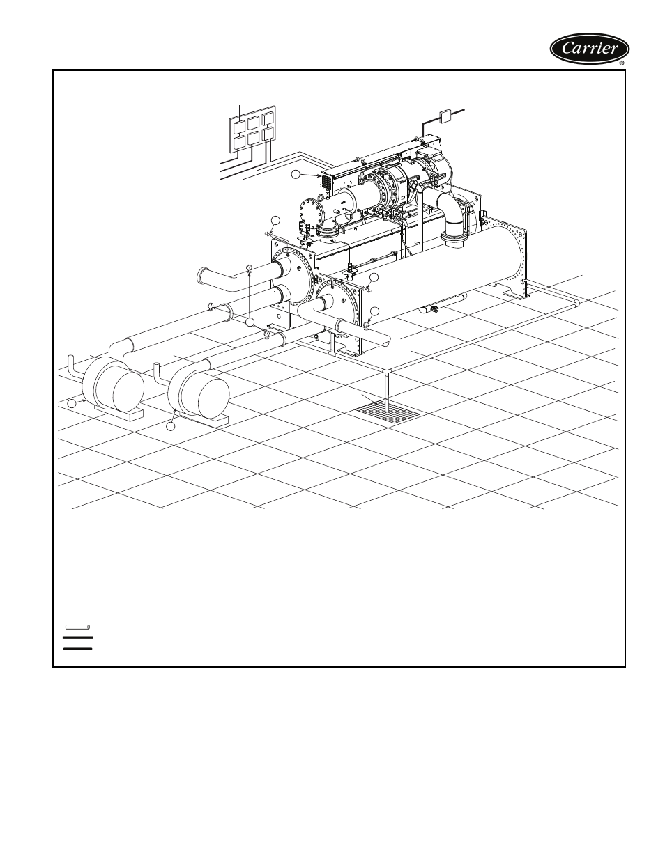
Typical piping and wiring
1
1
1
6
7
8
TO CHILLED LIQUID PUMP
TO CONDENSER LIQUID PUMP
TO COOLING TOWER FAN
2
1
MAIN COMPRESSOR
MOTOR POWER
FROM
COOLING
TOWER
FROM
LOAD
TO
COOLING
TOWER
TO
LOAD
3
3
9
9
DRAIN
5
4
LEGEND
1 — Disconnect
2 — Unit-Mounted VFD/Control Center
3 — Pressure Gages
4 — Chilled Liquid Pump
5 — Condenser Liquid Pump
6 — Chilled Liquid Pump Starter
7 — Condenser Liquid Pump Starter
8 — Cooling Tower Fan Starter
9 — Vents
Piping
Control Wiring
Power Wiring
NOTES:
1. Wiring and piping shown are for general point-of-connection only and are not
intended to show details for a specific installation. Certified field wiring and
dimensional diagrams are available on request.
2. All wiring must comply with applicable codes.
3. Refer to Carrier System Design Manual for details regarding piping techniques.
4. Wiring not shown for optional devices such as:
• remote start/stop
• remote alarms
• optional safety device
• 4 to 20 mA resets
• optional remote sensors
• kW output
• head pressure reference
5. Flow switches are NOT required.
23XRV CHILLER