Application data (cont), Vent and drain connections, Asme stamping – Carrier EVERGREEN 23XRV User Manual
Page 22: Relief valve discharge pipe sizing, Design pressures
22
Vent and drain connections
Nozzle-in-head waterboxes have vent and drain connec-
tions on covers. Marine waterboxes have vent and drain
connections on waterbox shells.
Provide high points of the chiller piping system with vents
and the low points with drains. If shutoff valves are provid-
ed in the main liquid pipes near the unit, a minimal amount
of system liquid is lost when the heat exchangers are
drained. This reduces the time required for drainage and
saves on the cost of re-treating the system liquid.
It is recommended that pressure gages be provided at
points of entering and leaving liquid to measure pressure
drop through the heat exchanger. Gages may be installed
as shown in Pressure Gage Location table. Pressure gages
installed at the vent and drain connections do not include
nozzle pressure losses.
Use a reliable differential pressure gage to measure pres-
sure differential when determining liquid flow. Regular gag-
es of the required pressure range do not have the accuracy
to provide accurate measurement of flow conditions.
PRESSURE GAGE LOCATION
ASME stamping
All 23XRV heat exchangers are constructed in accordance
with ASHRAE (American Society of Heating, Refrigerat-
ing, and Air Conditioning Engineers) 15 Safety Code for
Mechanical Refrigeration (latest edition). This code, in
turn, requires conformance with ASME (American Society
of Mechanical Engineers) Code for Unfired Pressure Ves-
sels wherever applicable.
Each heat exchanger and economizer (if equipped) is
ASME ‘U’ stamped on the refrigerant side of each vessel.
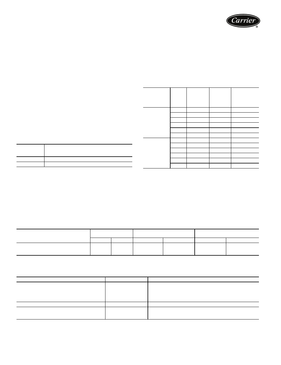
Relief valve discharge pipe sizing
See page 21 for number of relief valves.
Relief valve discharge piping size should be calculated
per the current version of the ASHRAE 15, latest edition,
code using the tabulated C factors for each vessel shown in
the table below.
23XRV RELIEF VALVE DISCHARGE PIPE SIZING
Carrier further recommends that an oxygen sensor be
installed to protect personnel. Sensor should be able to
sense the depletion or displacement of oxygen in the ma-
chine room below 19.5% volume oxygen per ASHRAE
15, latest edition.
Design pressures
Design and test pressures for heat exchangers are listed
below.
DESIGN AND TEST PRESSURES (23XRV)
*Nitrogen/Helium.
HEAT EXCHANGER MATERIAL SPECIFICATIONS
LEGEND
NUMBER
OF
PASSES
GAGE LOCATION
(Cooler or Condenser)
1 or 3
One gage in each waterbox
2
Two gages in waterbox with nozzles
HEAT
EXCHANGER
FRAME
SIZE
VESSEL
REQUIRED
C FACTOR
(lb air/Min)
RELIEF
VALVE
RATED
C FACTOR
(lb air/Min)
FIELD
CONNECTION
SIZE (FPT)
COOLER
30 to 32
43.4
70.8
1
1
/
4
35 to 37
49.5
70.8
1
1
/
4
40 to 42
50.4
70.8
1
1
/
4
45 to 47
57.4
70.8
1
1
/
4
50 to 52
53.7
70.8
1
1
/
4
55 to 57
61.1
70.8
1
1
/
4
CONDENSER
30 to 32
41.4
70.8
1
1
/
4
35 to 37
47.1
70.8
1
1
/
4
40 to 42
47.1
70.8
1
1
/
4
45 to 47
53.7
70.8
1
1
/
4
50 to 52
51.2
70.8
1
1
/
4
55 to 57
58.3
70.8
1
1
/
4
PRESSURES
SHELL SIDE
(Refrigerant)
STANDARD TUBE SIDE
(Liquid)
OPTIONAL TUBE SIDE
(Liquid)
psig
kPa
psig
kPa
psig
kPa
Leak Test at Design Pressure*
185
1276
150
1034
300
2068
Hydrostatic
—
—
195
1344
390
2689
Proof Test*
204
1407
—
—
—
—
ITEM
MATERIAL
SPECIFICATION
Shell
HR Steel
ASME SA516 GR 70
Tube Sheet
HR Steel
ASME SA516 GR 70
Condenser/Cooler Waterbox Cover
HR Steel
ASME SA516 GR 70, SA-36, or SA-285 GRC
Condenser/Cooler Waterbox Shell
HR Steel
ASME SA675 GR 60, SA-516 GR70, or SA-181 CL70,
SA-36, SA-675 GR70, SAE AME 7496
Tubes
Finned Copper
ASME SB359
Discharge/Suction
Pipe
Steel
ASME SA106 GRB
Flanges
Steel
ASME SA105
ASME — American Society of Mechanical Engineers
HR
— Hot Rolled
Application data (cont)