Bio-Rad Model EG-1 Econo™ Gradient Monitor User Manual
Page 10
7
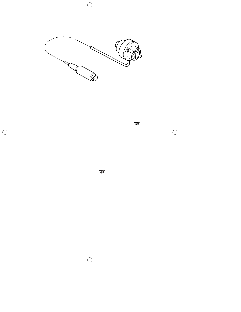
4.3 Flow Cell
Fig. 3.3. The flow cell.
Inlet/Outlet Ports
A male and a female luer fitting on either end of the
flow cell allow rapid tubing connection. The flow
cell can be used with flow in either direction. Note:
the luer fittings may be unscrewed and replaced with
1/4”-28 threaded flat-bottom fittings.
Signal Cable
For connection of the flow cell to the
socket on
the rear panel of the control unit.
Section 5
Setting Up
5.1 Flow Cell Installation
Place the flow cell as close as possible to the column outlet and/or any
other detection devices (e.g. a UV flow cell, if used) and connect the flow
cell’s Signal Cable to the flow cell
socket on the rear panel of the
control unit.
If the monitor is to be used in conjunction with the Model EM-1
Econo UV Monitor, connect the gradient monitor flow cell directly to the
inlet or outlet port of the portable optics module for optimal detection.
If the Econo Gradient Monitor is to be used with other UV monitors, the
flow cell should be placed as close as possible to the UV detection device.
5.2 Connecting the Model EG-1 Econo Gradient
Monitor to Recording Equipment
The Model EG-1 Econo Gradient Monitor is shipped with System
Cable 4, which connects the Econo Gradient Monitor to channel 2 of the
M7318150H 2/27/1 2:06 PM Page 7