Bio-Rad Model EM-1 Econo™ UV Monitor User Manual
Page 9
6
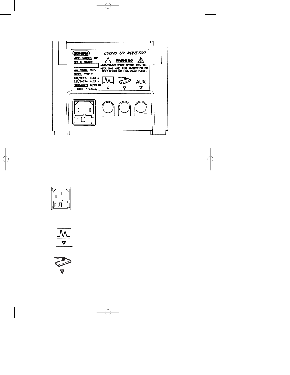
4.2 Rear Panel Sockets
Fig. 4.2. Rear panel sockets.
The rear panel of the Model EM-1 Econo UV Monitor control unit
contains four sockets for electrical connections (see Figure 4.2). Below
is a brief description of each socket. For a more technical description of
each socket, see Appendix C.
Socket
Function
Power Entry
IEC power entry module with
Module
four-position international voltage
selector. The monitor is shipped in
its 120 V or 220 V version. For
operation at other voltages, refer to
Section 5.1. Note: Power switch is
on bottom panel.
Signal Output For connection of chart recorders,
integrators, and computers to the
Model EM-1 Econo UV Monitor,
using standard Bio-Rad cables, see
Section 5.4 and Appendix C.
Optics Module 12-pin socket for connection of the
Socket
optics module.
M7318160G.qxd 05/08/2003 2:05 PM Page 6