Bio-Rad Model EM-1 Econo™ UV Monitor User Manual
Page 20
17
Appendix C
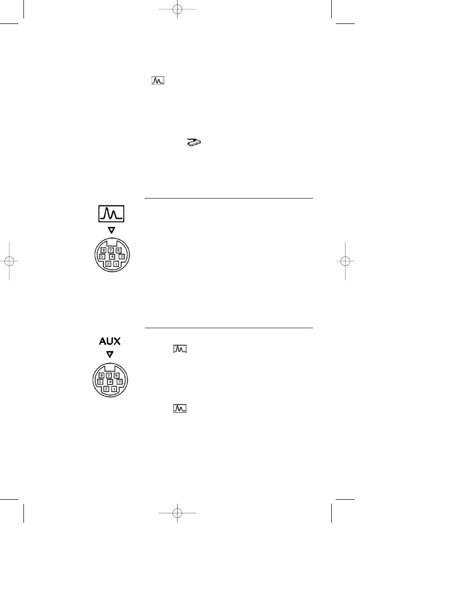
Rear Panel Connections
Both the signal
output and the AUX sockets are 8-pin circular
mini-DINs. The following information is provided for those wishing to
interface the Model EM-1 Econo UV Monitor with other equipment
such as integrators and non Bio-Rad fraction collectors. System Cable 7
may be used as a breakout cable, with an 8-pin mini-DIN at one end and
loose wires at the other.
Do not attempt to use the
socket for anything other than the
Model EM-1 Econo UV Monitor optics unit.
All digital inputs use TTL circuitry and are active LOW.
Pin #
Function
Notes
1
Connects to
Paper stop
AUX Pin 1
2
No Contact
3
No Contact
4
Integrator (+)
0 to 1 V = 0 to 2 AU
5
Chart Recorder (+)
0 to 1 V = Full scale
6
Connects to
Pen down
AUX Pin 6
7
Ground
8
No Contact
Pin #
Function
Notes
1
Connects to
Pin 1
2
Auto-Zero
3
Large Mark
Marks chart recorder
signal only
4
Integrator (+)
0 to 1 V = 0 to 2 AU
5
No Contact
6
Connects to
Pin 6
7
Ground
8
Small Mark
Marks chart recorder
signal only
pin
configuration
pin
configuration
M7318160G.qxd 05/08/2003 2:06 PM Page 17