Bio-Rad BioLogic LP System User Manual
Page 8
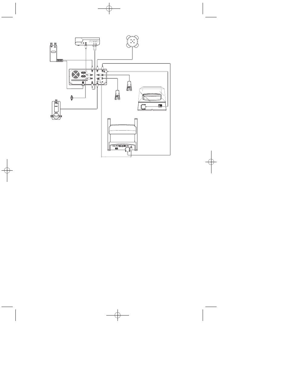
Fig. 2.
Section 5
Connecting a Chart Recorder
1. If you will be recording data with a Bio-Rad 1327 chart recorder
(discontinued item), set all chart recorder switches to the position
marked in green. For non-Bio-Rad chart recorders, set the chart recorder
to indicate full scale at 1 V.
2. Set a chart speed of 12 cm per hour.
3. Connect the cables for the chart recorder to the appropriate receptacles
on the rear panel.
4. Install the chart paper and pens in the chart recorder.
5. Note that two signal cables connect to the chart recorder.
a.
System cable 2 (Mini-DIN/Large DIN) connects between UV
CHART on the BioLogic LP and the single large DIN receptacle
on the 1327 chart recorder. This cable carries the UV signal for
channel 1, also the “paper stop” and “pen lift” signals. (For
non-Bio-Rad chart recorders, use system cable 4, and connect to
channel 1 of the chart recorder.)
Controller
Model 2110
Fraction Collector
OR
Model 1327
Chart
Recorder
System
Cable 2
Proportioning
Valve and
Mixer Module
UV Optics
Module
Conductivity
Flow Cell
System Cable 1
System Cable 15
System Cable 3
System
Cable 4
SV-5
Buffer
Select
Valve
SV-3
Column
Bypass
SV-3 Diverter Valver
(2110 Fraction
Collector)
MIXER
A
B
BioFrac
Fraction Collector
4
4006073D.qxp 8/17/2009 7:45 AM Page 4