Typical installation – B&G Zeus2 Glass Helm ZM Display 19 User Manual
Page 12
10 |
Connecting the display |
ZM Series User Manual
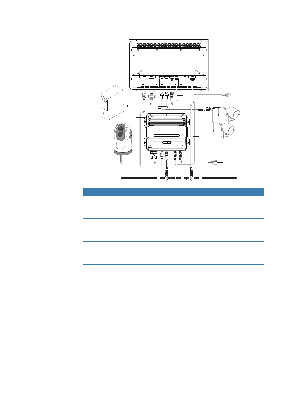
Typical installation
4
2
8
9
1
7
6
3
5
10
11
2
Key Description
1
ZM16-T or ZM19-T monitor
2
HDMI cable
3
DVI cable (eg. PC, non HDCP sources only)
4
Composite video cable (eg. video camera)
5
Zeus
2
Processor
6
FLIR® IR camera supplying video via
Zeus
2
Processor
7
Micro-C network bus
8
Serial cable - communicates touch control to
Zeus
2
Processor
9
Power cable - monitor
10
Micro-C network drop cable - allows software updating of monitor via
Zeus
2
Processor
11
Power cable -
Zeus
2
Processor
¼
Note:
peripheral devices in diagram do not necessarily show all required connections where
not directly related to ZM series monitor.
This manual is related to the following products: