User responsibility – Amico Nema 4 Master Alarm User Manual
Page 18
18
Amico Pipeline
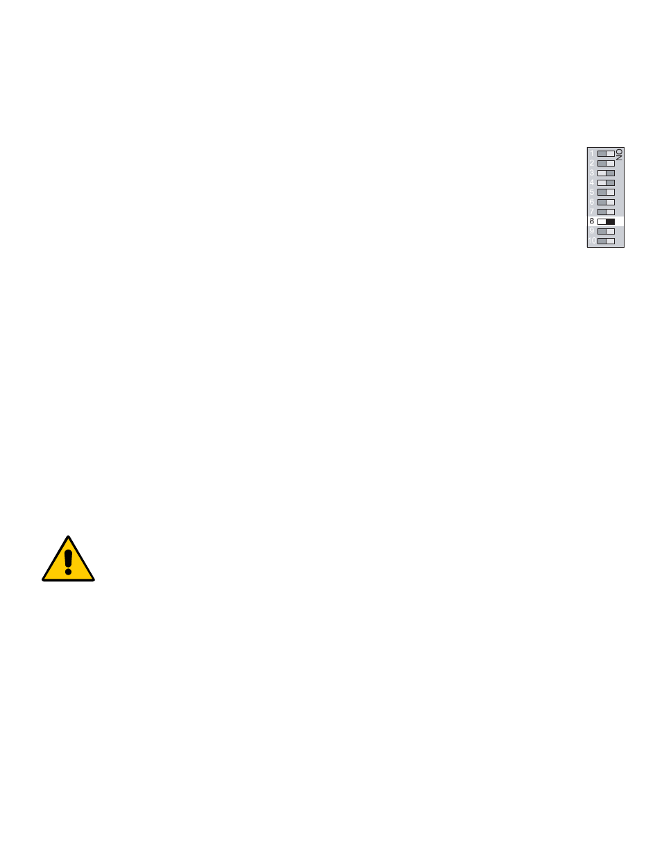
SETTING FACTORY DEFAULT
To quickly reset the module (Pressure or Vacuum) to the factory default settings as follows:
- Pressure: High set-point 60 Psi, Low set-point 40 Psi.
- Nitrogen & HP Air: High set-point 195 Psi, Low set-point 140 Psi.
- Vacuum: Low set-point 12 inchHg.
- No Repeat alarm, but set for 30 min..
1. Set switch #8 to the ON position.
2.
Turn the power off (wait 5 seconds) then back on.
3.
Set switch #8 to the OFF position.
The module is now in the default mode.
A m i c o M i c r o p r o c e s s o r B a s e d A l a r m
P a g e : 4
USER RESPONSIBILITY
The information contained in this Installation and Operation Maintenance
Manual, pertains only to the ALERT-2 microprocessor based digital alarm.
This product will perform to conformity with the descriptions contained in this
manual, when assembled, operated, maintained and serviced in accordance
with the installation instructions provided.
The alarm must be checked periodically. Parts that are broken, missing,
worn, distorted or contaminated, must be replaced immediately. Should such
repair or replacement become necessary, please contact Amico Corporation
or their distributors.
All alarms should not be repaired, or altered without prior written or verbal
approval of Amico Corporation or it’s distributors. Failure to comply will void
all warranty on the alarm.
Statements in this manual preceded by the words
WARNING
,
CAUTION
,
DANGER and
NOTE
are of special significance. Please read these sections
carefully.
WARNING:
denotes steps which can prevent injury.
CAUTION:
denotes steps which can prevent damage to equipment.
DANGER:
denotes steps which can prevent electrical shock to equipment
or to prevent serious injury and/or death.
SETTING GAS IDENTIFICATION SWITCHES
PLEASE NOTE: DO NOT tamper with switches #1, #2 and #3 on the dip-switch. Tampering with these positions will
result in an error message being displayed (EO2) and will disable the electrical interlock from the gas specific sensor.
Changes to these switches should only be done by properly trained personnel, when circuit
boards have to be changed in the field.
Switches # 1, #2 and #3 are used for the gas identification of the display module. These will be set at the factory and
should not be tampered with in the field.