Conventional liquid plumbing diagrams, Conventional system elements – Great Plains NP4000B Operator Manual User Manual
Page 169
Great Plains Manufacturing, Inc.
Appendix A - Reference Information
165
2014-05-14
417-199M
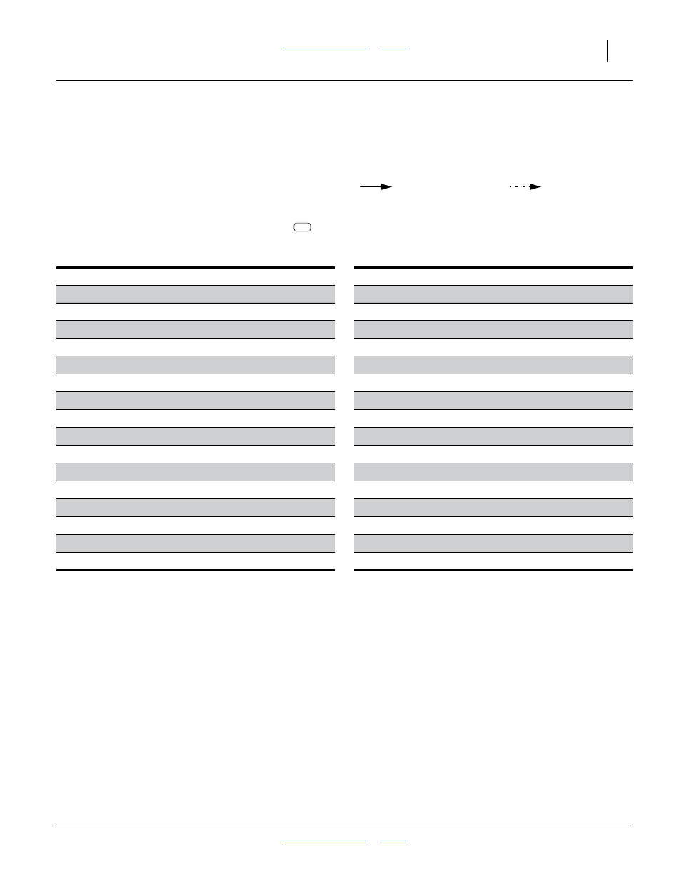
Conventional Liquid Plumbing Diagrams
• See page 30 for a component narrative.
Conventional System Elements
The hydraulic pump (variable rate) system (page 166)
differs from the ground drive (preset rate) system
(page 167) as follows:
• The ground drive system rate is set by simple drive
system sprockets. The hydraulic pump rate requires a
console which operates the flow control valve
.
• The ground drive system is single section. The
hydraulic pump has three sections.
L11. Application Tank
L28. Air Bleed Line
L12. Vented Tank Lid
L29. Flow Control Valve
L13. Tank Discharge Valves
L30. Flow Meter
L14. Tank Drain Elbow
L31. Section Valves
L15. Selector Valve
L32. Pressure Sensor
L16. Supply Inlet
L33. Boom
L17. Inlet Shut-Off Valve
L34. End Cap
L18. Strainer
L35. Boom Clamp
L19. Ground Drive Pump
L36. Shutoff Cap
L20. Pump Adjustment Dial
L37. Gasket
L21. Pump Adjustment Tool
L38. Orifice Plate
L22. Passive Manifold
L39. Nozzle Body
L23. Gauge Protector
L41. Drop Tubing
L24. Pressure Gauge
L42. Coulter Arm and Tubing
L25. Relief Valve
L43. Tine Nozzle
L26. Dump Line
L44. Tongue Release Handle
L27. Hydraulic Drive Pump
L45. Chain Anchor
Legend:
For more details on components L11 through L43,
see “Liquid System Narrative” on page 30.
Direction of Flow
Exception Flow
L30