Great Plains Yield-Pro 1625 Planter 2005 User Manual
Page 7
12/12/2005
402-181M
Great Plains Mfg., Inc.
7
Installation Instructions
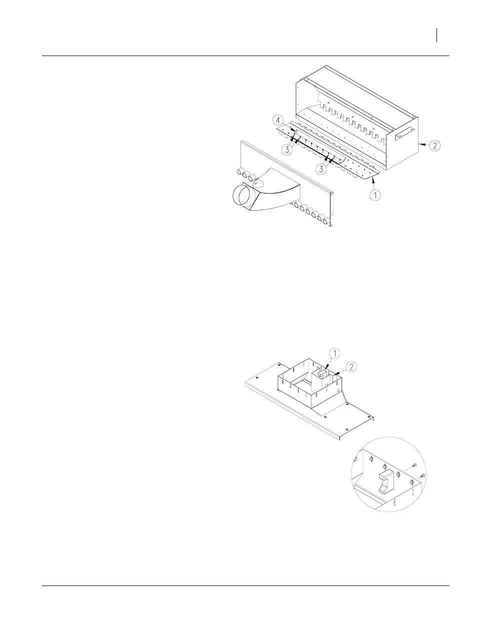
Refer to Figure 10
9.
Remove nine center screws (3) from front row
of screws securing manifold slat assembly (1)
to manifold (2).
10. Place air deflector (4) on top of manifold slat
assembly (1) with turned up edge toward rear
of manifold (2). Secure air deflector (4) to man-
ifold slat assembly (1) using the nine center
screws (3) removed in step 6 above.
Figure 10
Manifold Air Deflector
23463
Refer to Figure 11
11. Reinstall level sensor (1) and shroud (2) to new
manifold top weldment provided in kit. NOTE:
Orient level sensor as shown in inset. Use
hardware removed in step 4. Reconnect level
sensor to harness.
12. Reattach top manifold weldment to manifold
using bolts from step 2.
Figure 11
Manifold Shroud
23415
23489
NOTE: Front of manifold removed for clarity only. Do NOT
remove front of manifold.