Great Plains Yield-Pro 1625 Planter 2005 User Manual
Page 3
12/12/2005
402-181M
Great Plains Mfg., Inc.
3
Installation Instructions
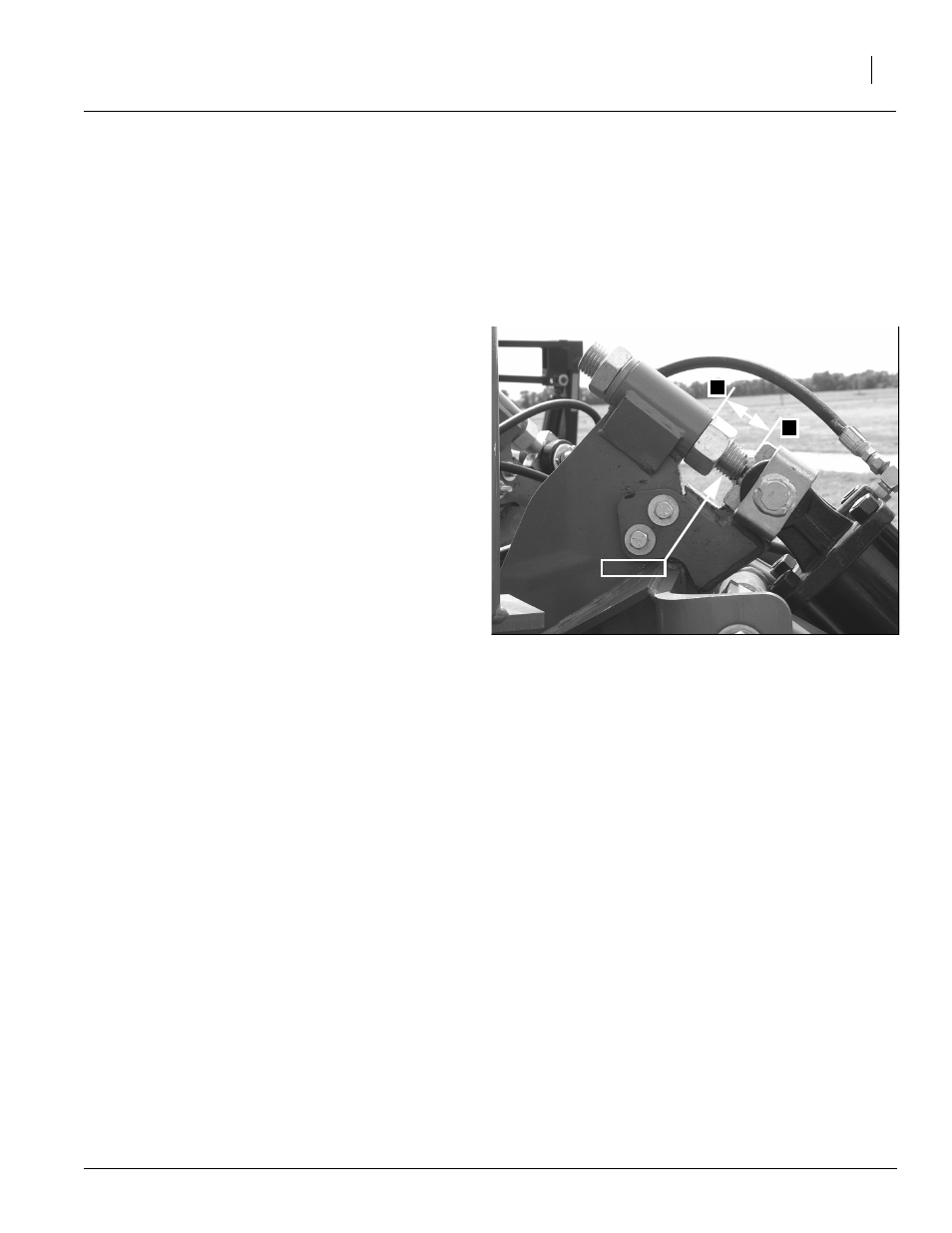
Refer to Figure 3
1.
Measure eyebolt threads from bottom of weld-
ment to bottom of eyebolt plate. Record measure-
ment to ensure eybolt is replaced at same length.
2.
Remove cotter pin and cylinder pin securing hy-
draulic cylinder to eyebolt weldment. Discard cyl-
inder pin. Keep other parts for reuse.
3.
Place eyebolt support weldment up under plate
against eyebolt. NOTE: Eyebolt should rest
against support weldment. Using center
punch, mark holes where support weldment bolts
to swivel caster mount.
4.
Remove cotter pin and cylinder pin securing op-
posite end of hydraulic cylinder to lower swivel
caster weldment. Discard cylinder pin. Keep oth-
er parts for reuse.
5.
Remove hydraulic cylinder from parallel arm
weldment.
NOTE: It is not necessary to disconnect hydraulic
hoses during installation of eyebolt support weld-
ment. However, disconnecting hydraulic hoses
may make installation easier.
6.
Remove eyebolt weldment from swivel caster
mount. Discard eyebolt. Keep other parts for re-
use.
7.
Drill out marked holes using 17/32" drill bit.
8.
Attach eyebolt support weldment using two
1/2-13 x 2 3/4 bolts, two 1/2 lock washers,
and two 1/2-13 hex nuts.
9.
Install new eyebolt weldment and adjust to length
recorded in step 1. Tighten eyebolt securely. Reat-
tach hydraulic cylinder to lower swivel caster weld-
ment and eyebolt weldment using new cylinder
pins provided in kit. Secure cylinder pins with cotter
pins previously removed.
NOTE: When installing new cylinder pins to reat-
tach cylinders, note location of grease outlet holes
in center of pins. Install pins so that holes are
pointing upwards or towards the cylinder main
body.
10. Repeat steps 1-9 on opposite side of planter.
11. Remove blocks supporting planter.
23404
Eyebolt
A
B
Figure 3
Install Eyebolt Support Weldment