Marker extension, Reading a marker extension diagram, Model 2020p marker extension – Great Plains 2525P Operator Manual User Manual
Page 83: 5 to tr30, 5 to 15
Great Plains Manufacturing, Inc.
Appendix
79
2013-05-10
118-231M
Marker Extension
The diagrams in this section show marker extension dis-
tances for all supported row unit configurations of all
drills covered by this manual.
Measure from the centerline of the outside row unit in
use on each side. Do not measure from a shut-off row
unit.
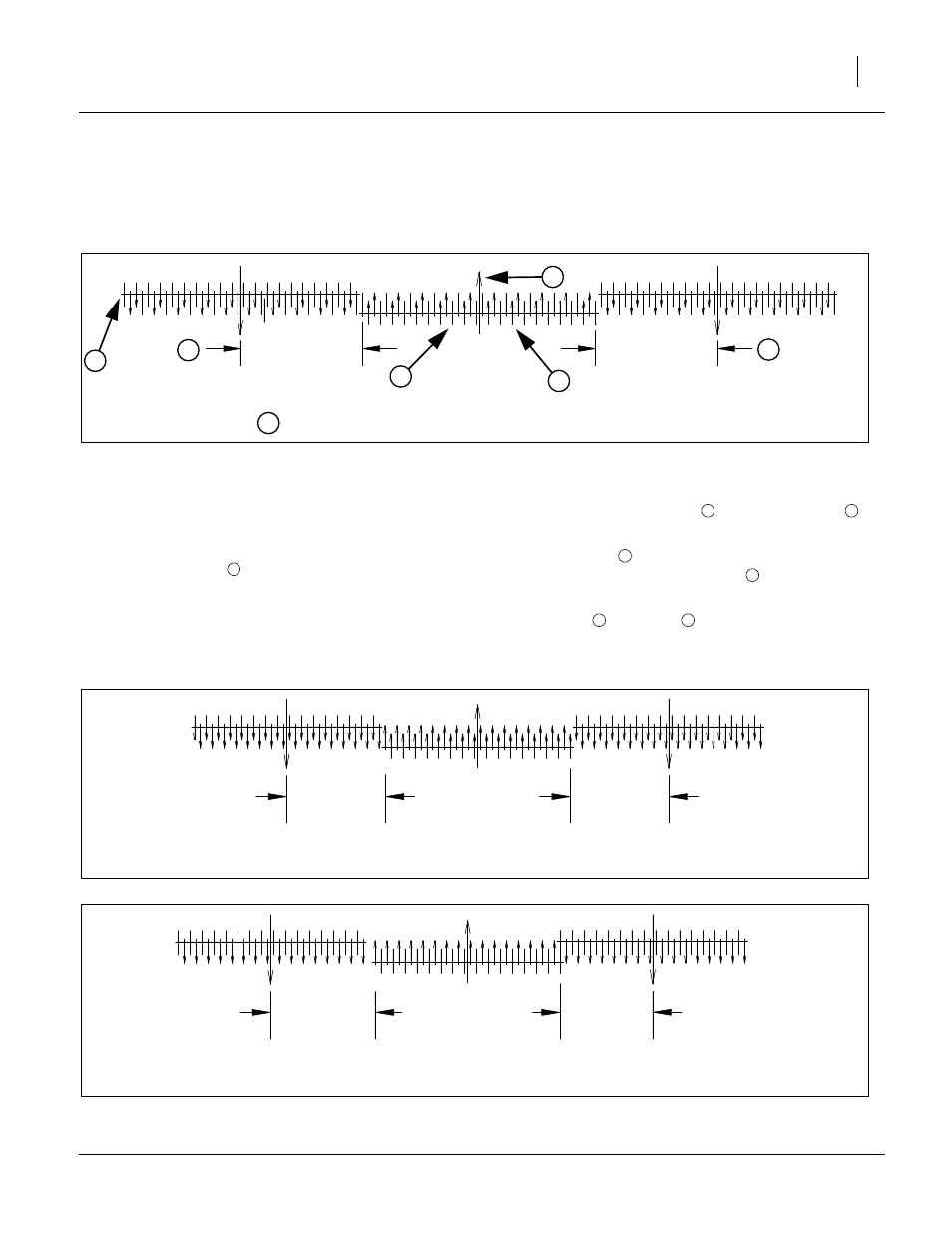
Reading a Marker Extension Diagram
Refer to Figure 88
Find the chart for your drill width (20ft or 25ft), row unit
Series (20 or 25), and row spacing.
The Figure title block
identifies the drill model, size,
row unit type, default row count, default row spacing, and
whether the diagram applies to a modified row spacing.
Each illustration shows three drills, their tool bars repre-
sented by the horizontal lines
. The large arrows
show the direction of travel.
The small arrows
show active row units. For modified
row spacings, the short vertical lines
(no arrows) show
which row units to shut off.
Note that Left
and Right
extension dimensions may
not be the same, and can be substantially unequal.
Model 2020P Marker Extension
7.5 TO TR30
153.75
153.75
Right Extension
142.50 in
361.95 cm
Left Extension
172.50 in
438.15 cm
Figure 88: Model 2x2xP-0000 2xft 2x Series 00-Row
00in Single-Row: as 00in Twin-Row
26231
SAMPLE DIAGRAM
1
3
4
5
7
6
2
1
2
3
4
5
6
7
7.5
123.75
123.75
123.75 in
314.33 cm
Figure 89: Model 2020P-3275 20ft 20 Series 32-Row
7.5in Single-Row: Standard Spacing
26232
123.75 in
314.33 cm
7.5 TO 15
116.25
131.25
131.25 in
333.38 cm
Figure 90: Model 2020P-3275 20ft 20 Series 32-Row
7.5in Single-Row: as 15in Single-Row
26232
116.25 in
295.28 cm