Clutch folding module (cfm) setup, Clutch folding module operation, 5 revolution test – Great Plains YP40F Operator Manual User Manual
Page 64: Of clutches 3
60
YP2425F/YP4025F
Great Plains Manufacturing, Inc.
403-362M
2013-03-25
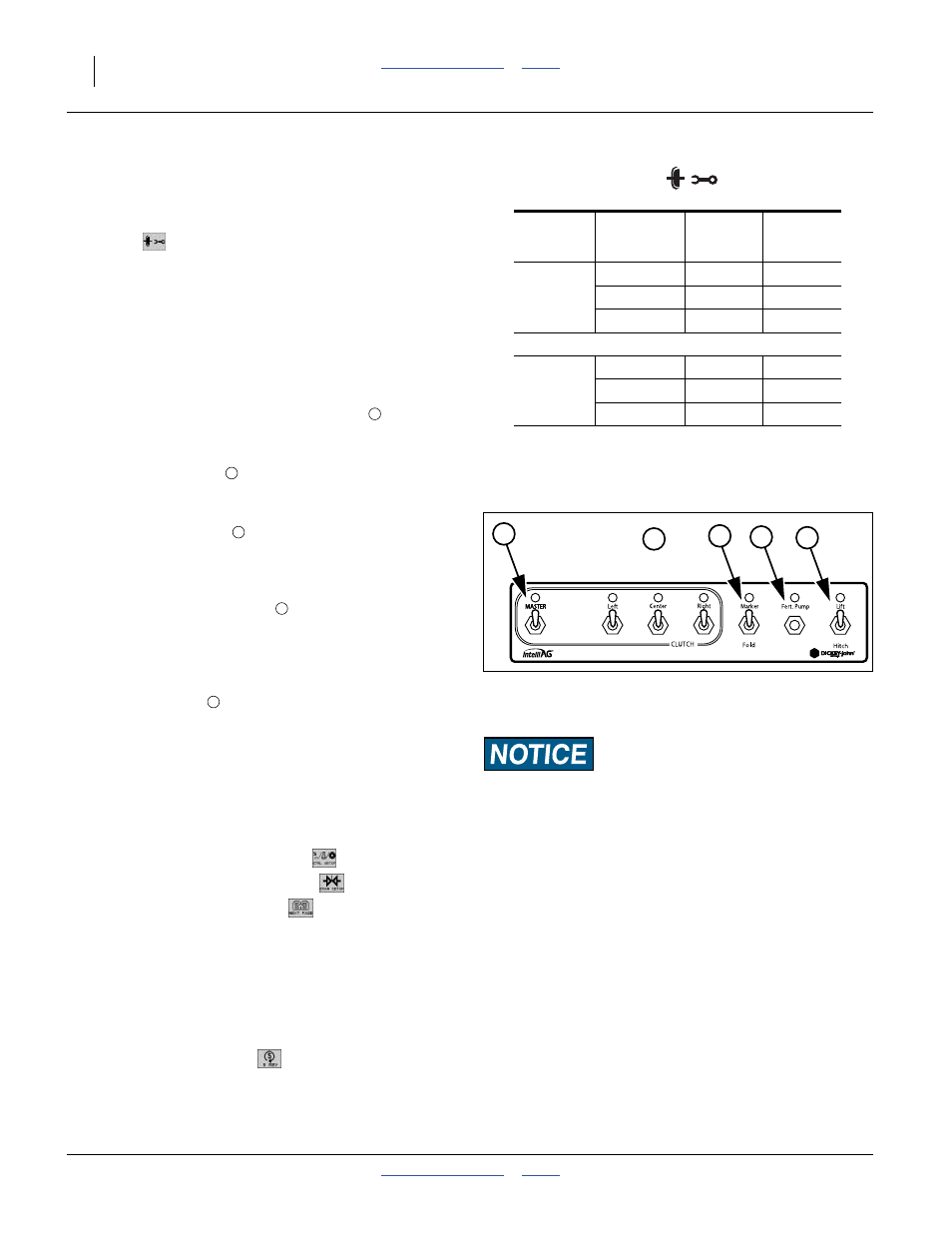
Clutch Folding Module (CFM) Setup
The CFM is installed in the cab to control row clutches,
marker, fold, fertilizer on/off, lift and hitch.
59. At the Main Work screen, press the Clutch CFG
button
to access the Clutch Configuration screen
and verify that the correct # of clutches are
configured for the system.
Note: The Clutch CFG button only appears as a top level
button when a planter output module and clutch
folding module are installed.
Clutch Folding Module Operation
Refer to Figure 25
60. The planter section “CLUTCH” controls
turn the
left, center, and right seeding clutch controls on and
off. Dry fertilizer application is unaffected.
61. The master switch
must be in the ON position to
activate any planter section. When a clutch control is
ON, a green light illuminates.
62. Marker/Fold Switch
should be in the UP (Marker)
position during planting. In the DOWN (Fold)
position, the switch controls the fold of the main
frame.
63. The fertilizer pump switch
usually has no function
on a YP2425F-2470, YP4025F-1630 and
YP4025F-1670 planter. Leave this switch in the
DOWN position (OFF).
64. If the planter has the optional hydraulic tongue, the
Lift/Hitch switch
should be in the UP (Lift) position
during normal operation (circuit controls implement
lift).
In the “Hitch” position (DOWN), the hydraulic circuit
controls the telescoping tongue in preparation of
folding the implement for transport.
5 Revolution Test
65. Press the Control Setup button
.
66. Press the Channel Setup button
.
67. Press the Next Page button
.
68. Ensure implement is raised before starting
5 Rev Test.
69. With brakes locked and transmission in PARK
position, start tractor engine.
70. Engage hydraulics and run engine at normal speed
until hydraulic fluid is at operating temperature.
71. Press the 5 Rev button
.
Note: Test Ground Speed and Row data must be entered
to perform test.
72. Press and hold remote test button to initiate 5 Rev Test.
OUTPUT
1-5
# OF
ROWS
ROW
#’s
6-11
12-16
LEFT
CENTER
RIGHT
5
6
5
# of Clutches 3
# of Clutches 3
Output
# OF
ROWS
ROW
#’s
YP4025F
Left
5
1-5
Center
6
6-11
Right
5
12-16
YP2425F
Left
9
1-9
Center
6
10-15
Right
9
16-24
1
1
{
2
3
4
5
Equipment Damage Risk (Hydraulic Tongue Only):
Lift/Hitch switch MUST be in the hitch position and hydraulic
circuit in FLOAT when transporting planter equipped with
hydraulic-operated tongue hitch.
Note: Lift/Hitch switch has no function if planter has
standard 3-point hitch operated tongue hitch.
Figure 25
Clutch-Folding Module
29718
2
3
4
5