Meter drive adjustments, Seed-lok lock up – Great Plains SR5030 Operator Manual User Manual
Page 19
17
Section 3 Adjustments
4/12/05
SR5030 Split-Row Planter 401-140M-A
Great Plains Mfg., Inc.
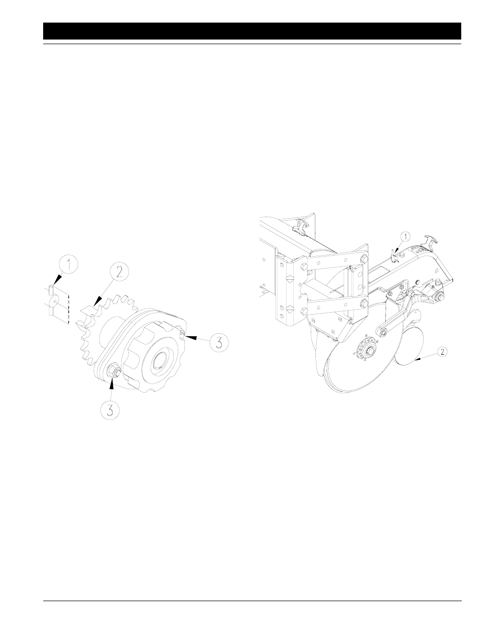
Meter Drive Adjustments
The meter clutch and meter-input shaft must be aligned.
Misalignment will cause meter malfunction and excessive
meter-housing wear. Periodically check vertical and hori-
zontal alignment of meter clutch and meter-input shaft.
1.
Latch hopper onto hopper support.
2.
Check that roll pin (1) in end of the meter-input shaft is
centered. When centered, equal amounts of the roll
pin will protrude from both sides of the shaft.
3.
Rotate meter-input shaft so that roll pin is vertical.
4.
Rotate the drive coupler (2) on meter clutch so that the
slots are vertical.
5.
Release meter clutch to engage meter-input shaft.
6.
If shafts are aligned vertically, the drive coupler will en-
gage with meter-input shaft freely and the roll pin will
extend equally on each side of the drive coupler. Dis-
engage the clutch and repeat steps, checking for hor-
izontal alignment.
17891
Figure 3-13
Vertical Alignment
7.
If drive coupler does not freely engage meter-input
shaft vertically or horizontally, loosen 5/16-inch nuts
(3) shown in Figure 3-13. Engage meter clutch. Align
meter clutch with meter-input shaft.
8.
Tighten 5/16-inch nuts to torque values listed on
Torque Values Chart, “Appendix,” page 31.
Seed-Lok Lock Up
Optional Seed-Lok firming wheels provide additional
seed-to-soil contact. The wheels are spring loaded and do
not require adjusting. In some wet and sticky conditions
the wheels may accumulate soil.
To lock up the firming wheels in wet conditions, raise the
planter. Push the lock-up handle (1) on top of the row-unit
body up into the position shown in Figure 3-14. Push up on
the firming wheel (2) until the wheel arm latches up.
To unlock the firming wheels, turn the lock-up handle back
to its 90-degree position.
17810
Figure 3-14
Seed-Lok Lock Up
NOTE: Side gauge wheel is removed in Figure 3-14 for
clarity.