Great Plains SR5030 Operator Manual User Manual
Page 14
12
Section 3 Adjustments
SR5030 Split-Row Planter 401-140M-A
4/12/05
Great Plains Mfg., Inc.
Side Gauge Wheels
The side gauge wheels have two, interrelated adjust-
ments:
• angle of side gauge wheel, and
• distance between side gauge wheel and opener disk.
Side Gauge
Wheel
Side Gauge
Wheel
Opener
Disks
Incorrect
Correct
Figure 3-4
Side Gauge Wheels
Adjust side-gauge-wheel angle so the wheels contact the
opener disks between 4 and 8 o’clock.
17812
8:00
4:00
Figure 3-5
Wheel-to-Disk Contact Area
At the same time, keep the side gauge wheels close to the
opener disks so openers do not plug with soil or trash but
far enough out so the disks and wheels turn freely.
To adjust side gauge wheels:
1.
Raise implement slightly to remove weight from side
gauge wheels.
2.
Loosen hex-head bolt. Move wheel and arm out on o-
ring bushing. See Figure 3-6.
Figure 3-6
17916
Loosen Hex-Head Bolt
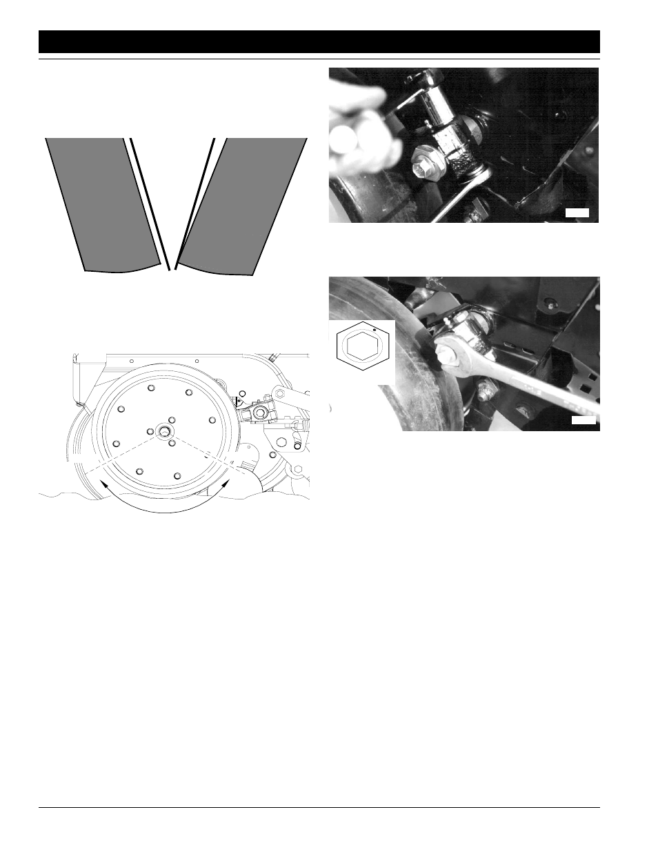
3.
Loosen pivot bolt. Turn hex adjuster so roll pin (1) is at
1 o’clock. Use this as the starting point for adjustment.
17914
Starting Point
Figure 3-7
Turn Hex Adjuster
4.
Move wheel arm in so side gauge wheel contacts
opener disk. Tighten hex-head bolt to clamp arm
around bushing and shank.
5.
Check the wheel-to-disk contact. Lift wheel and arm.
When let go, the wheel should fall freely.
• If wheel does not contact disk from 4 to 8 o’clock,
move hex adjuster until wheel is angled for proper
contact with disk.
• If wheel does not fall freely, loosen hex-head bolt
and slide wheel arm out just until wheel and arm move
freely. Retighten hex-head bolt.
6.
Keep turning hex adjuster and moving wheel arm until
the wheel is adjusted properly. When satisfied, tighten
pivot bolt to 110 foot-pounds.