Row unit adjustments – Great Plains SR5030 Operator Manual User Manual
Page 13
11
Section 3 Adjustments
4/12/05
SR5030 Split-Row Planter 401-140M-A
Great Plains Mfg., Inc.
Section 3
Adjustments
Row Unit Adjustments
Down Pressure
Springs provide the down pressure necessary for opener
disks to open a seed trench. The springs allow the row unit
to float down into depressions and up over obstructions.
You can adjust down pressure individually for each row
unit. Use only enough down pressure to cut the seed
trench and maintain proper soil-firming over seed. Exces-
sive down pressure will lead to premature wear on row-
unit components.
To adjust, lift T-handle shown in Figure 3-1.
• Move T-handle back to increase spring pressure.
• Move T-handle ahead toward tractor to decrease
spring pressure.
17718
Figure 3-1
Row Unit Spring Adjustment
Refer to the charts below for the amount of spring pres-
sure at the opener for each spring setting.
Down Pressure Charts
Medium-Duty Spring Package
Pounds Pressure
First Holes (Closest to Tractor)
85
Second Holes
100
Third Holes
115
Fourth Holes
135
Fifth Holes (Closest to Hopper)
155
Heavy-Duty Spring Package
Pounds Pressure
First Holes (Closest to Tractor)
155
Second Holes
175
Third Holes
205
Fourth Holes
225
Fifth Holes (Closest to Hopper)
245
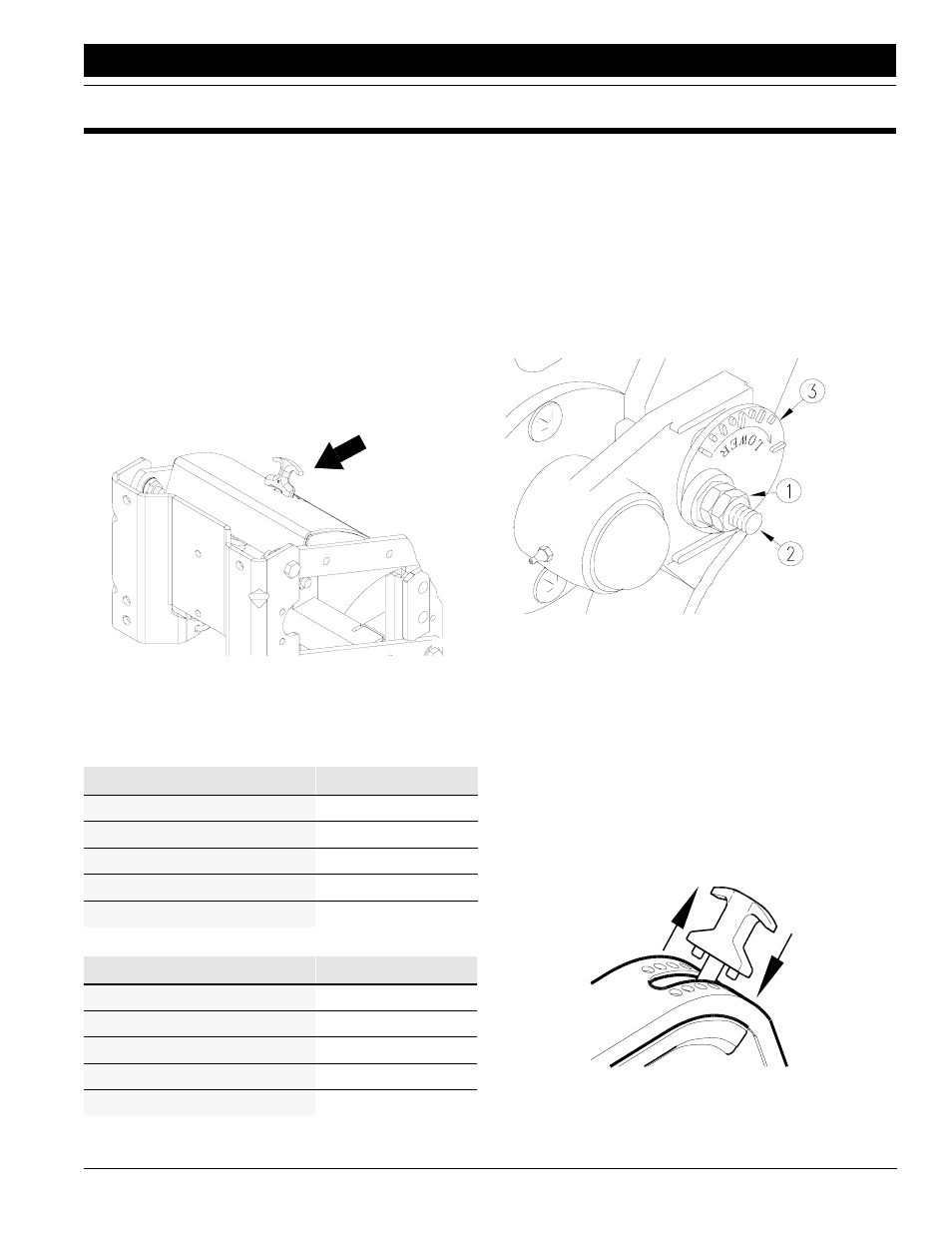
Coulter Depth
Optional coulters allow row unit to penetrate tough ground
conditions. Adjust coulters to run at the same depth as the
opener disks.
1.
To adjust coulter depth, loosen 3/4-inch jam nut (1)
and 3/4-by-3-inch hex bolt (2). See Figure 3-2.
2.
By turning cam hex (3), rotate cam casting to the de-
sired height. Each notch represents about 1/4 inch of
depth.
3.
Torque bolt and jam nut to values recommended on
Torque Values Chart, “Appendix,” page 30.
15053
Figure 3-2
Row Unit Mounted Coulter
Opener Seeding Depth
Seeding depth is controlled by gauge wheels mounted on
the sides of the opener disks.
To adjust seeding depth:
1.
Raise planter to remove weight from side gauge
wheels.
2.
Raise and move T-handle shown in Figure 3-3.
• Move T-handle forward to decrease seeding depth.
• Move T-handle back to increase seeding depth.
3.
Move T-handles on all row units to the same location.
12345
Figure 3-3
Opener Depth Adjustment
The Eliminator involves two, interrelated adjustments: