Install arm assemblies, Install left arm assembly, Asteners finger-tight until step 20 – Great Plains NTA2007HD Assembly Instructions User Manual
Page 5
Great Plains Mfg., Inc.
Installation Instructions
5
2013-10-10
113-850M
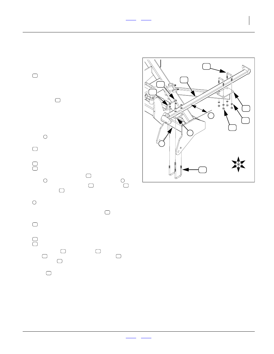
Install Arm Assemblies
Install Left Arm Assembly
Refer to Figure 6 (which, for clarity, depicts only the arm
subframe - what is installed is an entire arm assembly)
13. Select one new:
(which is an entire left arm assembly)
To reduce weight during installation, and reduce
arm length during system charge, remove the third
stage arm (
, not shown).
14. Leave in place any straps holding the arm in the
fully folded position. Remove only such straps as
are necessary to free the arm from the shipping
crate or pallet.
Secure the arm in a hoist, with the forward mounting
plate
facing down.
15. Select two new:
FNS-02291 806-080C 5/8x4-1/16x6-1/2 Sq-
U-Bolt for 4x5 U-BOLT 5/8-11 X 4 1/32 X 6
and four sets new:
16. Position the arm assembly
plate
over the left end of the front tool bar
.
Loosely secure with U-bolts
, lock washers
and hex nuts
17. Adjust the horizontal position to:
18.26 cm (7
3
⁄
16
in,)
measured from the outside face of the wing end
plate to the left side of the subframe
tube.
18. Select two new:
5/8-11x3-1/16x3-1/2 Sq-U-Bolt for3x2
and four sets new:
19. Using U-bolts
, lock washers
nuts
, loosely secure the arm subframe
to the
mount plate
20. As necessary, adjust the final position of the
mount
so that the arm subframe is parallel to the
wing end plate.
Secure all fasteners to torque spec.
Null4:
Null4:
Figure 6
Install Left Arm (Subframe Shown)
31339
U
D
F
B
L
R
4
6
23
5
23
5
23
55