Install supply hoses – Great Plains NTA2007HD Assembly Instructions User Manual
Page 11
Great Plains Mfg., Inc.
Installation Instructions
11
2013-10-10
113-850M
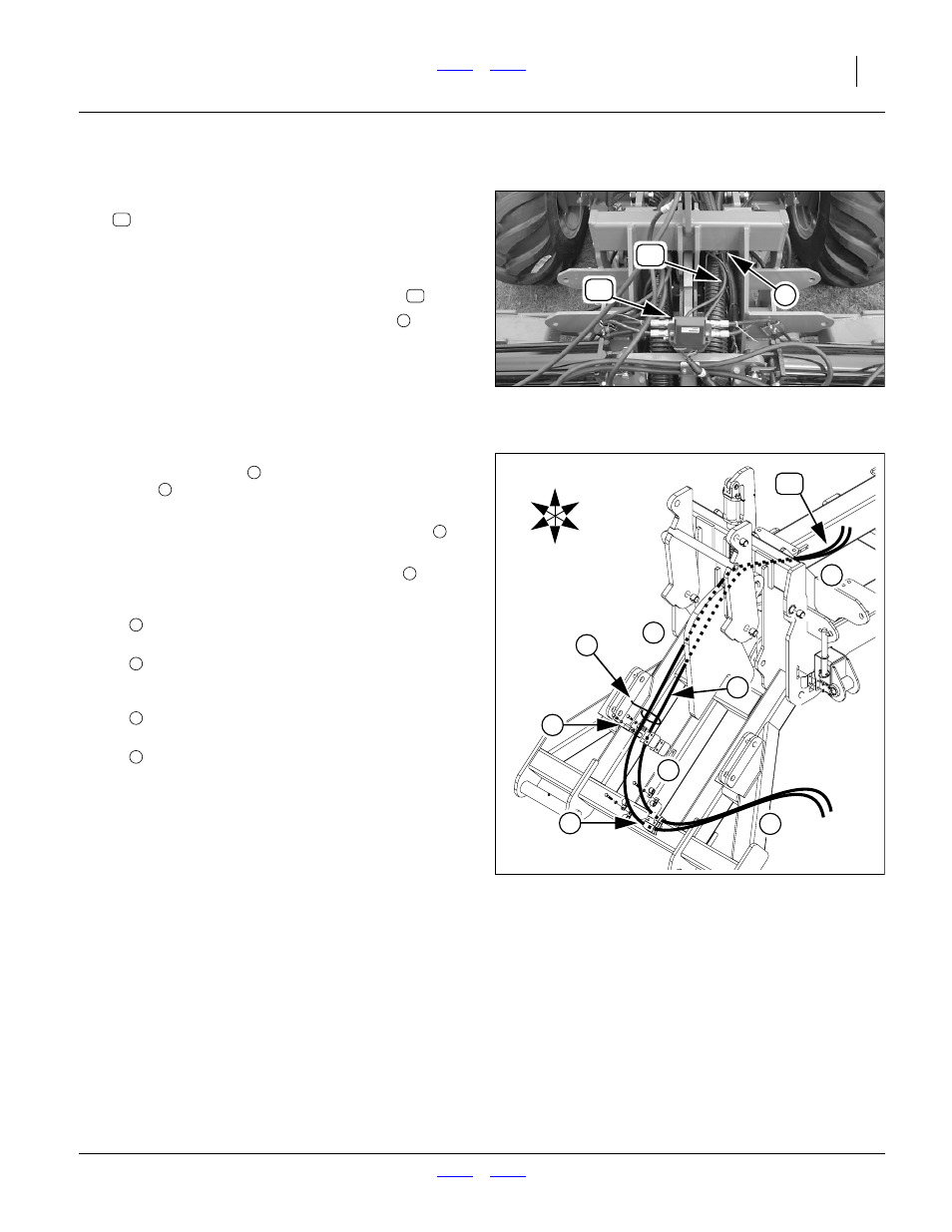
Install Supply Hoses
Refer to Figure 14
63. Select two new:
HP-9JF100.375
3/8" HOSE X 100" 9/16 JICF ENDS
As prepared at step 40 through step 43.
64. Connect the FJIC ends of the hoses to the MJIC
ports on the bottom of the sequence valve
.
65. Route the hoses through the hose clamp
mounted upper the right side of the top hitch tool
bar. Leave clamps lightly snug at this time, to allow
for sag and slack adjustment at step 69.
Null4:
Refer to Figure 15
66. Route the left hose
clamp
, which may have only one available clamp-
ing location.
67. Use a tie wrap to loosely secure the right hose
to
the left hose near the mid clamp.
68. Route both hoses through the front clamp
69. Adjust sag and slack:
70. Tighten all clamps.
Null4:
Null4:
Figure 14
Valve to Hitch Hose Routing
31347
72
1
74
72
74
1
•
Allow enough slack near the sequence valve to
allow hose disconnection.
•
allow most of the slack between the top and
mid clamps. The distance between them
increases during lift.
•
Allow only enough slack between the mid and
front clamps to prevent hose kinking.
•
Allow enough slack at the QD end of the hoses
to allow easy disconnection. If the implement is
lowered during marker assembly, there will be
ample slack for the small change in distance from
the front clamp to the panel outlet during raise/
lower.
Check that all slack is clear of moving parts.
Null4:
Figure 15
Lower Hitch Hose Routing
31348
U
D
F
B
L
R
3
2
4
5
72
a
b
c
d
2
5
a
b
c
d