Install depth control valve and o-ring fittings, Attach hose clamps and hose wraps – Great Plains TC5319 (S/N A1420X+) Predelivery Manual User Manual
Page 15
Great Plains Manufacturing, Inc.
Assembly
11
03/06/2014
566-224Q
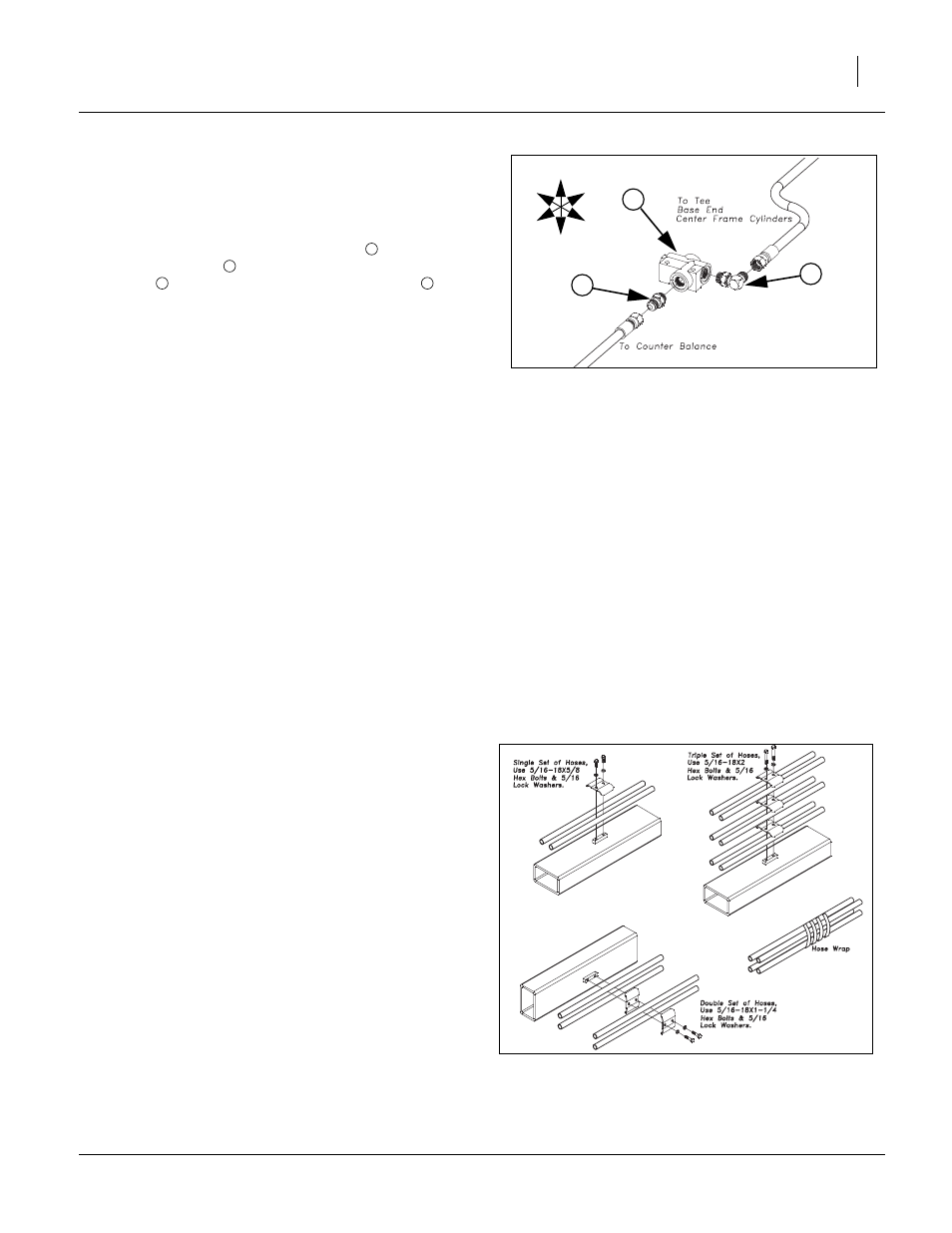
Install Depth Control Valve and O-Ring Fittings
Refer to Figure 10
42. Follow same procedure (steps 33-40) for installing fittings
into depth control valve.
43. Thread elbow (adjustable stud) fitting
into side port of
depth stop valve
. Thread straight (non- adjustable stud)
fittings
into front port of depth control valve
.
Note: Do not over tighten as this could cause damage to valves.
Tighten as shown, See “Hydraulic Connectors and
Torque” on page 18 or proper torque value.
44. Route hoses as shown in layout section in Appendix.
45. When the JIC hoses are routed, follow the following proce-
dure for hooking up and tightening.
a.
Inspect for possible contamination or damage from
shipping or handling. Sealing surface should be
smooth. Annular tool marks of (100uin) concentric
with thread permissible.
b.
Lubricate the threads and the entire surface of the
cone with hydraulic fluid or a light lubricant.
c.
Align mating components for hand connection and
turn flare nut until sealing surfaces make full contact.
d.
Torque nut to the values shown in “Torque Value
Chart” page 23. If a wrench pad is provided next to
nut, place a second wrench on pad to prevent flare
from rotating while being torqued.
e.
When torquing nut onto a straight flared fitting, it may
be necessary to also place a wrench on the flared fit-
ting wrench pad to prevent it from turning during
assembly.
46. Alternate Assembly Method for JIC.
a.
If torqued method not possible, then proceed to
steps b-e.
b.
Lightly wrench tighten the nut until there is firm resis-
tance.
c.
Place a wrench on wrench pad next to nut as near
the 6 0’clock position as possible.
d.
Place second wrench on nut as near the 3 o’clock
position as possible.
e.
Turn nut clockwise to no less than the 4 o’clock posi-
tion and no more than the 6 o’clock position.
Required rotation generally decreases as size
increases.
Refer to Figure 11
Attach Hose Clamps and Hose Wraps
47. When all the hoses are hooked up and tightened prop-
erly, put hose clamps on hoses as shown.
48. Install hose wraps on hoses as needed.
Note: Be sure and get hoses and light wiring harness fas-
tened properly so they do not drag. Check to be sure
there is enough slack in hinge area when folding ma-
chine the first time.
Figure 10
Depth Control Valve Fittings
41671
U
D
F
B
L
R
2
1
3
3
1
2
1
Figure 11
Hose Clamps & Wraps
41583
- TC5323 (S/N A1420X+) Predelivery Manual TC5321 (S/N A1420X+) Predelivery Manual TC5317 (S/N A1420X+) Predelivery Manual TC5315 (S/N A1420X+) Predelivery Manual TC5313 (S/N A1420X+) Predelivery Manual TC5115 (S/N A1420X+) Predelivery Manual TC5113 (S/N A1420X+) Predelivery Manual TC5111 (S/N A1420X+) Predelivery Manual TC5109 (S/N A1420X+) Predelivery Manual