Hydraulic hose assembly, Install rebound valve and o-ring fittings, Bypass valve – Great Plains TC5319 (S/N A1420X+) Predelivery Manual User Manual
Page 14
10
TC5109-5323
Great Plains Manufacturing, Inc.
566-224Q
03/06/2014
Hydraulic Hose Assembly
Note: Once the hitch and trusses are installed, the hydraulics
may be hooked up. All models will be shipped with hoses
attached to hitch. The hoses will be capped off and will
need to be hooked up to fittings. The hose ends and fit-
tings will be marked with color ties and will need to be
hooked up with matching colors. Be sure to get the hoses
hooked correctly or hydraulics will not work correctly, Re-
fer to hydraulics in parts manual for hydraulic layouts.
Install Rebound Valve and O-Ring Fittings
Refer to Figure 8
33. Inspect all components for damage or contamination
during shipping.
34. Lubricate o-ring and threads on fitting.
35. Thread straight (non- adjustable stud) fittings
into
ports V1 and V2 of rebound valve
, finger tight
Note: Do not over tighten as this could cause damage to
valves. Tighten as shown, See “Hydraulic Connectors
and Torque” on page 18 or proper torque value.
36. Follow steps 34 and 35, then proceed to steps below.
37. Looking at fitting from end with nut/washer/o-ring assem-
bly, turn nut clockwise as far as possible.
38. Using wrench, Thread 45 degree elbow (adjustable stud)
fittings
into port C1 and C2 of rebound valve
. until
the washer touches the port spot face. Continue turning
fitting until washer touches thread nearest wrench pad.
39. Back off fitting counterclockwise not exceeding one revo-
lution until it is oriented in the correct position.
40. Place wrench on the wrench pad of fitting to prevent fit-
ting from turning.
Note: Do not over tighten as this could cause damage to
valves. Tighten as shown, See “Hydraulic Connectors
and Torque” on page 18 or proper torque value.
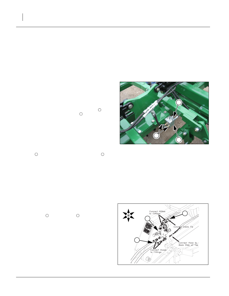
Bypass Valve
Refer to Figure 9
41. Attach hoses
to bypass valve
(Models 5317-5323
only). Hoses and fittings will have color ties to get hoses
hooked up properly.
Note: See TC5317-TC5323 Hydraulic Down Pressure in “Op-
erator’s Manual” for adjusting bypass valve.
Figure 8
Rebound Valve Fittings
42621
2
1
3
3
1
2
1
Figure 9
Bypass Valve
42642
U
D
F
B
L
R
1
2
1
1
2
- TC5323 (S/N A1420X+) Predelivery Manual TC5321 (S/N A1420X+) Predelivery Manual TC5317 (S/N A1420X+) Predelivery Manual TC5315 (S/N A1420X+) Predelivery Manual TC5313 (S/N A1420X+) Predelivery Manual TC5115 (S/N A1420X+) Predelivery Manual TC5113 (S/N A1420X+) Predelivery Manual TC5111 (S/N A1420X+) Predelivery Manual TC5109 (S/N A1420X+) Predelivery Manual