Assembly, Gangs, Truss, depth stop tube & wing stop assembly – Great Plains TC5319 (S/N A1420X+) Predelivery Manual User Manual
Page 12
566-224Q
03/06/2014
8
TC5109-5323
Great Plains Manufacturing, Inc.
Assembly
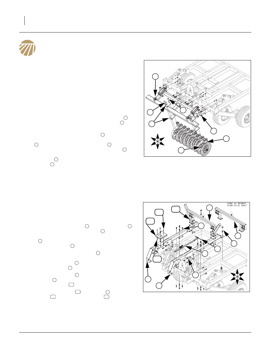
Gangs
Refer to Figure 5
Note: Folding models will be shipped with wings attached in
transport position, but shown in field position or no wings
for clarity. The large bolts will be shipped either in frame
or part assemblies in proper locations. The smaller bolts
will be shipped in a box. See “Parts Manual for part num-
bers and description of parts. The gangs will come pre-
assembled on gang tube. Refer to machine layout in Ap-
pendix for proper gang placement.
18. Start by attaching the center gang bar assembly
, with a
fork lift or overhead hoist with 3/4 x 2 hex bolts
, 3/4 lock
washers and 3/4 nuts.
19. Carefully move the gang assemblies
into the machine
so the c-flexes are just under the gang bar mount assem-
bly
as shown. Install a mounting pate
above and
below gang tube. Secure with a 3/4 x 6 hex bolt
(rear
hole of plate) and 3/4 lock nut. Now align holes of gang
bracket plate
on bottom side of c-flex, secure with 5/8 x
7 hex bolts
, 5/8 lock washers and 5/8 nuts.
20. Bolts may be tightened to specs, See “Torque Values
21. Repeat same procedure for the wings after the hitch and
hydraulics have been installed so the wings may be
unfolded.
Truss, Depth Stop Tube & Wing Stop
Assembly
Refer to Figure 6
22. Attach rear of RH hitch truss
and LH hitch truss
with
1 1/4 x 8 1/2 Gr. 8 special thread bolt
, 1 1/4 lock washer
and 1 1/4 nut. Secure middle plate with 3/4 x 2 1/2 hex
bolts
, 3/4 lock washers and 3/4 nuts. Secure front plate
with 3/4 x 2 hex bolts
, 3/4 lock washers and 3/4 nuts.
23. Slide front of depth stop assembly
through square hole
of bracket welded on left side of LH truss. Align rear holes
of depth stop assembly
on torque tube lever, secure
with 1/2 x 3 hex bolt
, 1/2 lock washer and 1/2 nut.
24. Attach center wing stop
(Folding Models) or rigid smv &
light bracket
(Rigid Models) to top plates of trusses with
5/8 x 1 1/2 hex bolts
, 5/8 lock washers and 5/8 nuts.
25. Mount the manual pack
to RH truss
plate with 1/4 x
1 hex bolts
, mini end press wheels
, 1/4 lock wash-
ers and 1/4 nuts.
26. Bolt may be tightened to specs, See “Torque Values
Figure 5
Gangs
42724
U
D
F
B
L
R
5
7
1
2
4
3
6
1
2
3
1
6
4
7
5
Figure 6
Truss, Depth Stop & Wing Stop
42727
U
D
F
B
L
R
1
8
4
3
12
2
9
5
11
13
6
7
10
1
2
3
4
5
6
6
7
8
9
10
11
1
12
13
- TC5323 (S/N A1420X+) Predelivery Manual TC5321 (S/N A1420X+) Predelivery Manual TC5317 (S/N A1420X+) Predelivery Manual TC5315 (S/N A1420X+) Predelivery Manual TC5313 (S/N A1420X+) Predelivery Manual TC5115 (S/N A1420X+) Predelivery Manual TC5113 (S/N A1420X+) Predelivery Manual TC5111 (S/N A1420X+) Predelivery Manual TC5109 (S/N A1420X+) Predelivery Manual