Description of the steering sensor module, Steering sensor module – Great Plains 3PYPA Planters User Manual
Page 6
6
Great Plains Manufacturing, Inc.
Tractor Sensor Module Installation
401-768M
06/16/2011
Description of the Steering Sensor Module
Steering Sensor Module
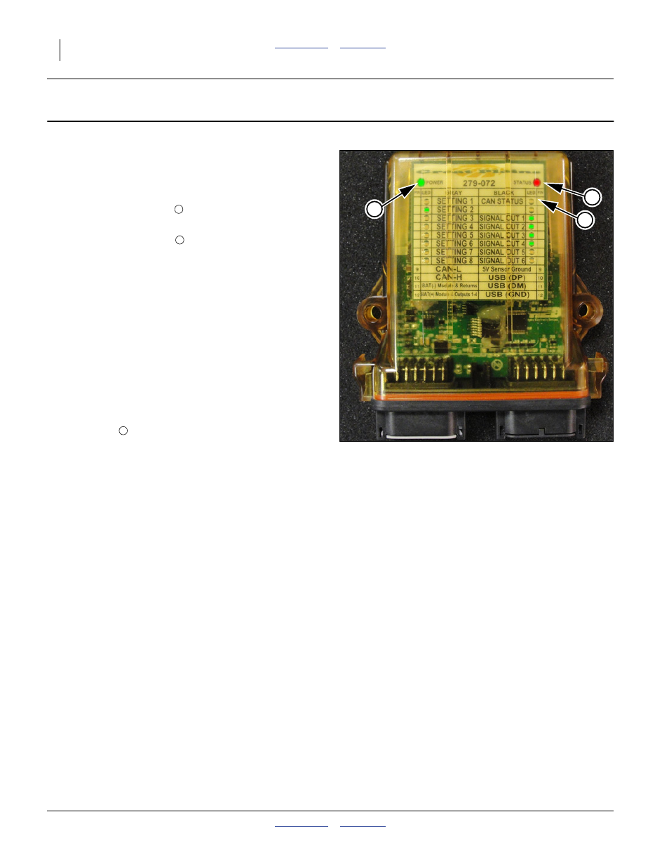
The module has a translucent case through which a
series of lights are visible.
Refer to Figure 13
The light labeled POWER
is solid green when pow-
ered up.
The light labeled STATUS
indicates the heartbeat of
the program. This light is a flashing red light when the
program is operating properly.
SETTING 1 This is a constant green light when the mod-
ule detects itself being connected to a John Deere tractor
through the steering angle sensor.
SETTING 2 This is a constant green light when the mod-
ule detects itself being connected to a Case/New Holland
tractor through the Steering Angle Sensor.
SETTING 3 This is a constant green light when the mod-
ule detects itself being connected to a John Deere tractor
via the ISObus diagnostics port.
SETTING 4 through 8 For future use.
CAN STATUS
This is a constant green light when the
module detects the CAN signal.
SIGNAL OUT 1 through 6 These lights are active when
the module is directly connected to the tractor Steering
Angle Sensor (Setting 1 and 2). The number of lights lit is
based on the angle of the wheels. The intent of the
series of lights is, as the steering wheel is turned from
full left to full right the number of Signal Out lights illumi-
nated will change. This change in the number of lights
illuminated lets the operator know the signal from the
tractor is changing.
Since the value of the signal is based solely on the trac-
tor, at any given position of the steering wheel the num-
ber of lights illuminated may not be the same.
EXAMPLE: When the system is connected to Tractor X a
hard left turn may have only SIGNAL OUT 1 illuminated.
As the steering wheel is turned toward a hard right, a
progressive number of SIGNAL OUT lights may illumi-
nate. Whereas if the system is connected to Tractor Y, a
hard left turn may have several SIGNAL OUT lights illu-
minated instead of just one. And as the steering wheel is
turned toward a hard right a progressive number of SIG-
NAL OUT lights go out instead of light up.
When installing the module no settings need to be
changed and no calibration of the module is required.
When the module is installed and the steering system is
powered on the appropriate lights illuminate. At this point
follow the instructions for steering system calibration
located in the Operator Manual (3PYP manual number
401-312M or 3PYPA manual number 401-647M).
Null4:
Figure 13
Electronic Sensor Module
(shown with Setting 2 active)
31877
2
1
3
1
2
3