Descriptions of module components, Electronic module, Module master harness (input) – Great Plains 3PYPA Planters User Manual
Page 2
2
Great Plains Manufacturing, Inc.
Tractor Sensor Module Installation
401-768M
06/16/2011
Descriptions of Module Components
Electronic Module
Refer to Figure 3
The electronic module reads the steering angle informa-
tion from either the CANbus or directly from the sensor
then converts the information to a PWM (percent duty
cycle) signal that is compatible with the Great Plains
3PYP steering system and outputs the signal to the
3PYP steering system.
Place the electronic module in a location in the tractor
cab where:
• it will not get damaged
• close enough to the 3PYP Steering System
Switch Box to connect the power wire.
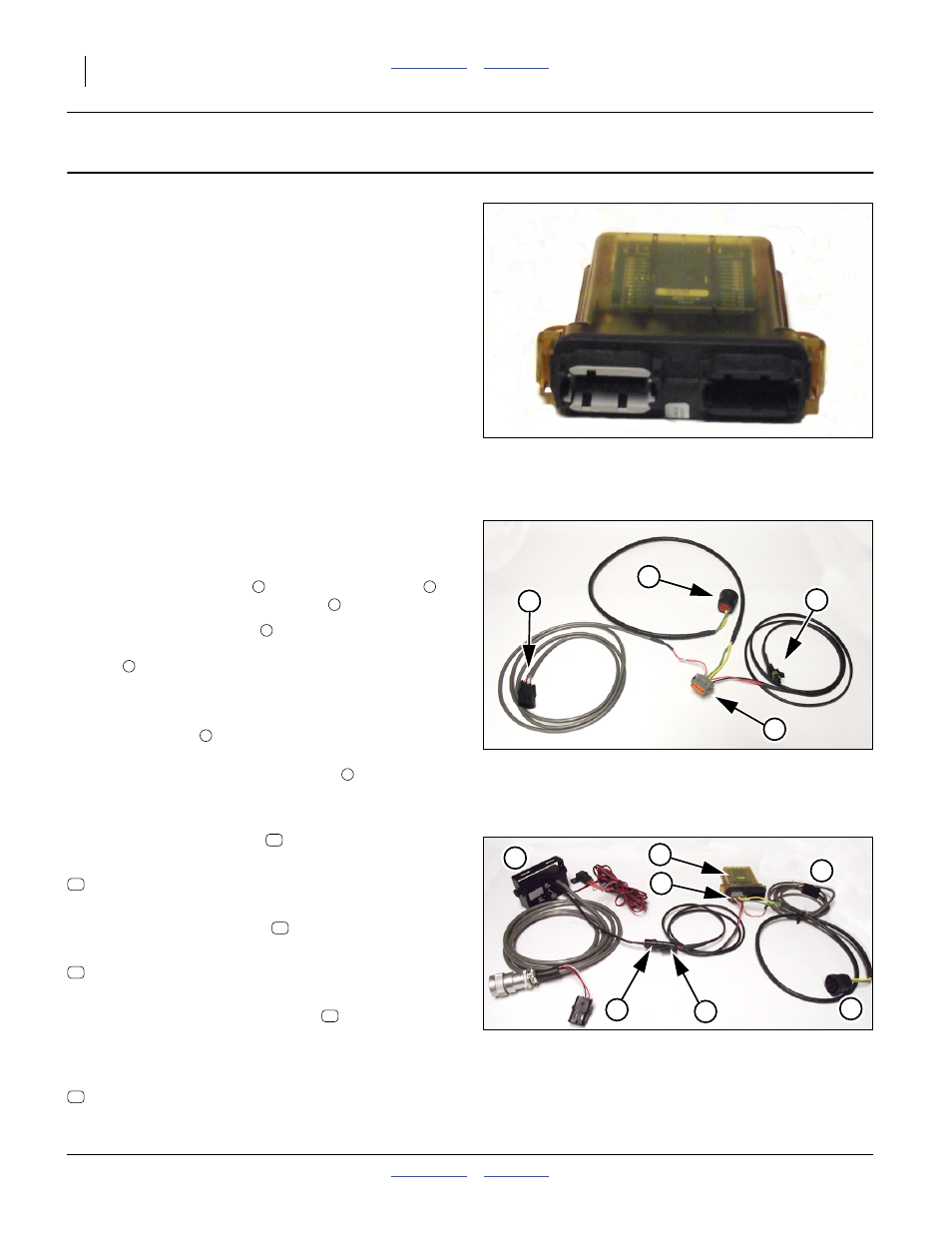
Module Master Harness (Input)
Refer to Figure 4 and Figure 5
The input harness provides power to the module by con-
necting its 2 pin connector
to the 2 pin connector
from the Steering System Switch Box
.
The gray colored connector
on the harness attaches
to the gray colored plug on the translucent electronic
module
.
Select only one of the two other connectors to plug in:
(The selection is tractor specific.)
• the ISObus
(connects to the tractor ISO diag-
nostics port) OR
• the Tractor Wheel Angle Sensor
(3 pin connec-
tor that connects to one of the optional adaptor
harnesses listed below)
Null4:
John Deere Track Tractors
Required for all John Deere tracked tractors.
833-546C HARNESS JD WHEEL ANGLE SENSOR
John Deere Wheel Tractors
Required for non-ISO compatible wheeled tractors.
833-548C HARNESS JD WHEEL ANGLE SENSOR
Case/New Holland Wheel Tractors
Required for all Case and New Holland tractors that are
factory equipped as auto-steer ready or have factory
installed auto-steer.
833-544C HARNESS CNH WHEEL ANGLE SEN-
Null4:
Figure 3
Electronic Module
31832
Null4:
Figure 4
Module Master Harness
Signal Power IN (Gray end)
31833
3
1
2
4
1
5
7
2
6
3
4
Null4:
Figure 5
Master Harness Connected
to both the Electronic Module
and Steering Switchbox
31740
5
6
1
4
3
7
2