Bleeding lift and marker hydraulics – Great Plains 1300 13-Foot Operator Manual User Manual
Page 47
Great Plains Manufacturing, Inc.
Maintenance and Lubrication
43
2014-04-15
175-157M
Bleeding Lift and Marker Hydraulics
To function properly, the hydraulics must be free of air.
With air in the system, the hydraulics will move in jerky,
uneven motions. If you install or replace a hydraulic
component, follow these steps.
1.
Check the fluid level in the tractor hydraulic reservoir.
Bleeding the hydraulics with a low fluid level will draw
air into the system.
Refer to Figure 40 (depicting a cylinder support block
- you
can also set the cylinder vertically, pinned in the mount)
2.
If markers are installed, disconnect the rod ends of
both cylinders and lay the markers on the ground.
Support the cylinders so that the rod ends are free of
obstructions.
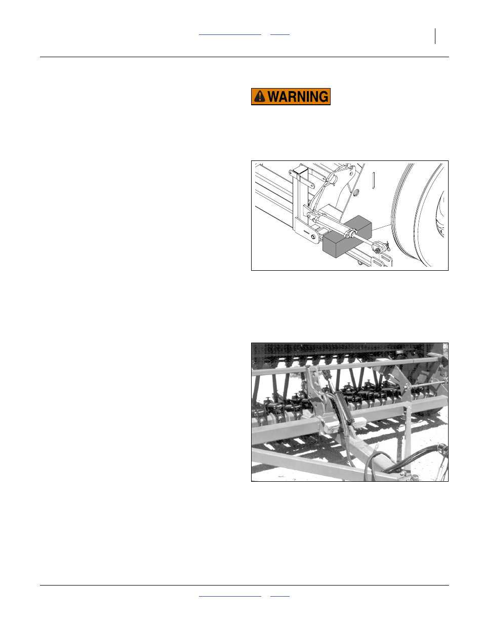
Refer to Figure 41
3.
Lower the openers to the ground. Unpin the rod end
of the cylinder from the floating lug. Wire, block up, or
otherwise safely support the cylinder so the rod will
not contact anything when fully extended.
4.
Operate the lift circuit to retract the lift cylinder.
If markers are installed, this will also retract one
marker cylinder.
5.
Loosen a JIC or NPT connection between the hoses
and fittings of:
• lift cylinder base end (cylinder retracted)
• marker cylinder base end (cylinder retracted)
6.
With the tractor idling, slowly work the tractor remote
lever as if extending the lift cylinder. As oil seeps
from a fitting, stop extension and tighten each hose
connection.
7.
Continue working the lever until the lift cylinder and
active marker cylinder rods are completely extended.
8.
Loosen a JIC or NPT connection between the hoses
and
• lift cylinder rod-end fitting
• marker cylinder rod end
9.
With the tractor idling, slowly work the tractor remote
lever in the opposite direction as if retracting the lift
cylinder. As oil seeps from a fitting, stop retraction
and tighten each hose connection.
10. If markers are installed, repeat step 4 through step 9
for the other marker side.
11. Reconnect the marker cylinders. Cycle the system to
fold and lock each marker with its pin.
12. Continue working the lever until the lift cylinder is
completely extended. Re-pin the cylinder to the
floating lug.
Note: When bleeding cylinders, begin with them
retracted (loosening base end connection), and
end with them extended (loosening rod end
connection).
Figure 40
Marker Cylinder Bleed
36276
Crushing and Sharp Object Hazards:
Keep all persons well clear of markers during lift/lower
marker fold/unfold operations. Un
-pinned markers fold and
unfold when the lift circuit is extended or retracted. Markers
have multiple pinch points. Lowering arms can crush. Marker
disks are sharp.
Figure 41
Opener Lift Cylinder Supported
16675