Opener frame down-force, Spring down pressure-all openers, Spring down pressure–all openers – Great Plains 1300 13-Foot Operator Manual User Manual
Page 36: Opener frame down, Force
32
1300 and 1300F
Great Plains Manufacturing, Inc.
175-157M
2014-04-15
Opener Frame Down
-
Force
To properly adjust seeding depth, you need an
understanding of how the opener frame, opener springs,
disks and press wheels work. The opener frame
adjustment affects all rows at once.
Refer to Figure 27 and Figure 28
The openers are mounted on a pivoting tube
.
A hydraulic cylinder mounted on a floating lug controls
the openers. Springs on the opener bodies provide down
pressure for the opener disks to cut a seed furrow. An
adjustable pivot-stop pin
floating lug and thereby controls spring length and down
pressure on all openers.
Changing the position of the pivot-stop pin changes
opener down-pressure across the drill. You can also
change the spring length or mounting height of individual
openers, such as in tire tracks.
Press wheels are mounted on the opener bodies behind
the opener disks, and perform two functions:
• They close the furrow and firm the seed bed. To
provide consistent seed firming, the press wheels are
free to move down from their normal operating
position. This maintains pressing action even if the
opener arm lifts at obstructions.
• The press wheels control opener depth. The higher
the press wheels run, the deeper seed is placed.
Spring Down Pressure–All Openers
The amount of down pressure needed for the opener
disks to penetrate the soil varies with field conditions.
The objective in selecting a pivot-stop pin hole, and a
press wheel height, is to achieve the desired planting
depth while keeping the drill frame and the row unit
frames level with the ground.
Note: The setting of the pivot-stop pin
interacts with
the setting of the press wheel height. When
adjusting one, recheck the other.
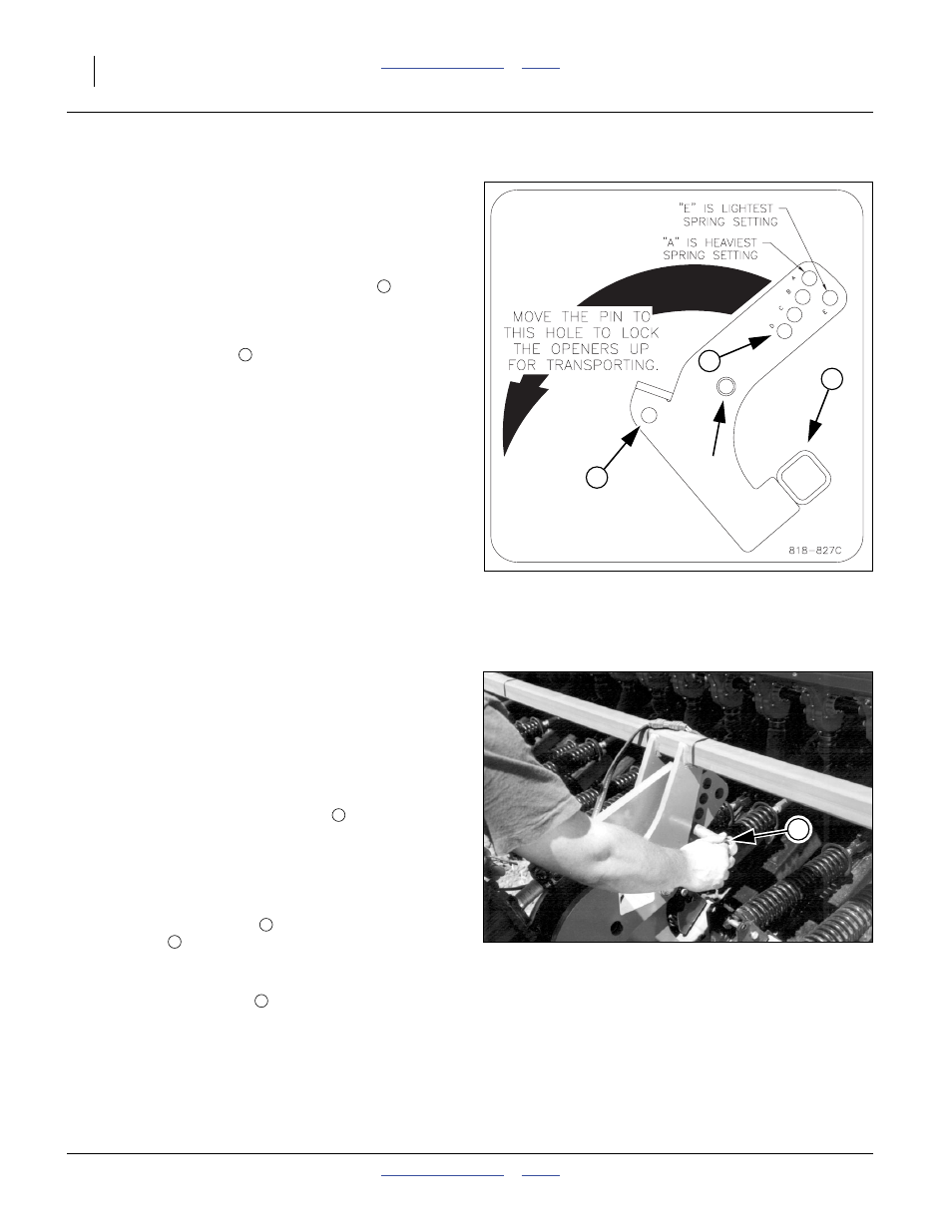
To increase or decrease all-rows spring down pressure:
1.
Raise the drill (to free the pin).
2.
Move the pivot-stop pin
.
The holes
in the floating lug are lettered:
A provides the greatest down pressure and
E provides the least.
As the pin is moved to hole
for transport, keep records
of what hole is optimal for fields and conditions worked.
Note: To maintain consistent opener down pressure, fully
extend the hydraulic cylinder each time you lower
the openers.
Figure 27
Down-Pressure Decal
818827C
1
3
Pivot
Point
4
1
2
Figure 28
Adjusting Down-Pressure Pin
16652
2
2