Front gang assembly 3500-4000 – Great Plains 4000TM Predelivery Manual User Manual
Page 21
Great Plains Manufacturing, Inc.
Assembly
17
11/06/2012
586-288Q
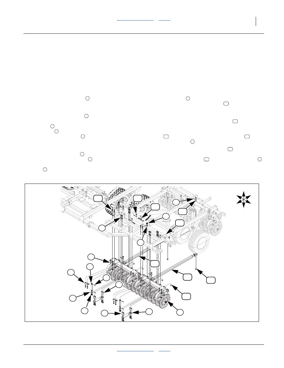
Front Gang Assembly 3500-4000
Note: The center and wing gang assemblies will install
the same. The only difference is, that the gang
assemblies and turnbuckles will be different from
center to wings. Cylinder base end will be hooked
to ear on center and wing frames. See machine
layouts in appendix section for proper gang loca-
tions. See wing gang bar & fold assembly 3500-
4000 for complete parts breakdown. You will prob-
ably need to hook all hydraulics up, See “3000
Hydraulic Wing Lift & Gangs” on page 18
through See “4000 Hydraulic Fold” on page 24
and charge systems before installing gang assem-
blies, See “Purging Hydraulic System 3000-
4000” on page 27.
Refer to Figure 21
75. Position gang assemblies
in correct location on
floor or ground and carefully lower machine down to
gang assemblies.
76. Install the gang pivot bolt
through aligned tubes
on gang bars and brace bars. Secure with 1 1/4 flat
washers
(one on top and one on bottom), 1 1/4
slotted nut
(one on top and one on bottom) and
two 3/16 x 2 cotter pins
. Tighten bolts snug,
torque to 350 to 400ft-b. Cotter pins may be bent
over to secure.
77. Install the round tubes
(four on each gang bar)
between bottom front plate
(slotted hole toward
rear) and plate on brace bars. Install the 3/4 x 6 hex
bolts
, 3/4 lock washers and 3/4 nuts.
78. Install bracket
on bottom side of gang bar plate,
secure with 5/8 x 3 1/2 hex bolts
, 5/8 lock wash-
ers and 5/8 nuts.
79. Install either 586-444S turnbuckle assembly (center
section) or 586-445S (wing sections)
, adjustable
end on ear on front of rear gang bars and fixed end
on ear of front gang bars. Secure with 1 x 3 1/4 clevis
pin
, 1.5 x 1.00 x 0.075 machine washer
and 3/
16 x 2 cotter pin
.
80. Now the rod end of gang cylinders
may be
hooked up with the 1 x 3 1/8 clevis pin, 1.5 x 1.00 x
0.075 machine washer
and 3/16 x 2 cotter pin
.
81. Bolt may be tightened to specs, See “Torque Values
Chart” on page 36 and all cotter pins may be bent.
1
2
3
4
5
6
7
8
9
10
11
12
13
5
14
13
5
Figure 21
Front Gang Assembly 3500-4000
42881
9
8
1
7
1
3
6
14
13
11
13
15
10
6
2
5
U
D
F
B
L
R
4
12
14
5
11
4
3