Wing, brace bar & fold 3500-4000 – Great Plains 4000TM Predelivery Manual User Manual
Page 20
16
1200-4000TM
Great Plains Manufacturing, Inc.
586-288Q
11/06/2012
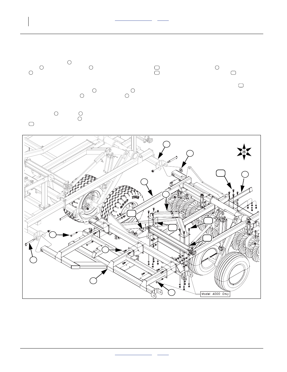
Wing, Brace Bar & Fold 3500-4000
Refer to Figure 20
68. Attach wing brace
to front of wing frame assem-
blies
with 3/4 x 2 hex bolts
and 3/4 x 7 hex bolts
(inside plates, bottom holes) and (outside plate,
bottom outside hole, model 4000 only), 3/4 lock
washers and 3/4 nuts.
69. Attach wing frame assemblies
to center frame
with the wing hinge pins
, 1 1/4 flat washers
(rear side of wing hinge tubes only, do not use on
wing brace bar) and 1 lock nuts.
70. Attach front
and rear
wing stops to plates on
wing frame assemblies
with 5/8 x 1 1/2 hex bolts
, 5/8 lock washers and 5/8 nuts.
71. On models 4000, attach base end of fold cylinders
to wing frame assemblies
with 1 x 3 1/8 pins
, 1.5 x 1.00 x.075 machine washer
and 3/16 x 2
cotter pin.
72. Do not hook up rod end of fold cylinders
until sys-
tem is purged of air. See “Purging Hydraulic Sys-
tem 3000-4000” on page 27.
73. Bolt may be tightened to specs, See “Torque Values
74. Model 4000, attach outside wing, See “Wing &
Brace Bar 1800-3000 & 4000” on page 15.
1
4
2
3
4
5
6
7
8
9
4
10
11
4
12
13
11
Figure 20
Wing, Brace Bar & Fold 3500-4000
42880
6
11
3
8
U
D
F
B
L
R
7
4
1
3
2
10
5
9
10
13
12