Great Plains 2515P Marker Option User Manual
Page 5
3/19/2003
113-685M
Great Plains Mfg., Inc.
5
Installation Instructions
Carrier Assembly, 2015 and 2515
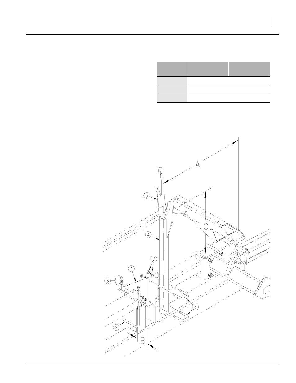
To assemble carrier onto bean machine frame, re-
fer to Figure 7. Refer to Table 1 for mounting
dimensions.
Figure 7
Transport Carrier Assembly
17796
Dimension
20-Foot
Bean Machine
25-Foot
Bean Machine
A
38 inches
55 1/2 inches
B
3 1/16 inches
2 5/8 inches
C
29 inches
36 3/8 inches
Table 1
Carrier Mounting Dimensions
1.
Assemble transport-carrier mount (1) on
bean machine frame. Center mount A inches
from outside end of bean machine frame. Use
1/2 x 6 1/32 x 7 inch
u-bolts (2), flat washers, lock washers and
hex nuts (3). Slide mount forward so its lead-
ing edge is about B inches ahead of front
edge of bean machine frame tube.
2.
Bolt transport carrier (4) to transport-carrier
mount so top surface of saddle (5) is about C
inches above top of bean machine frame
tube. Secure transport carrier with 1/2 x 2 x 3
inch u-bolts (6), lock washers and hex nuts
(7).
3.
After installing and bleeding hydraulics, trans-
port carrier may require further adjustment.
When folded, the second marker section
should rest in the transport-carrier saddle.
Refer to Marker Adjustments in the operator’s
manual.