Great Plains 2515P Marker Option User Manual
Page 3
3/19/2003
113-685M
Great Plains Mfg., Inc.
3
Installation Instructions
Marker Assembly, 2515 and 2515P
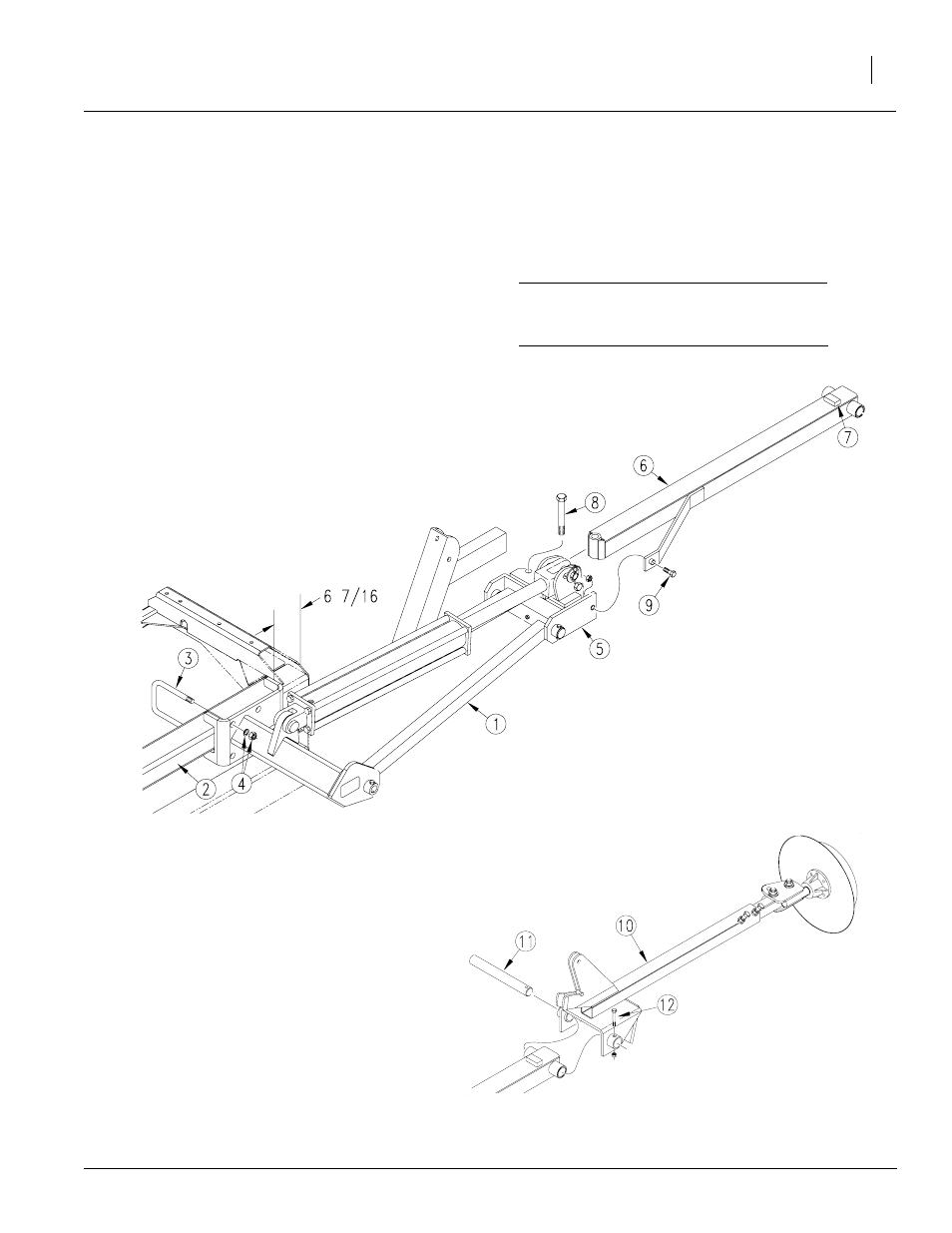
Refer to Figure 4.
Figure 4
Marker First and Second Section Assembly
17728
1.
Lower bean machine into field position. Allow
15 feet of clearance from each end of bean
machine box for marker assembly.
2.
Attach first marker section (1) to 4 x 5 inch
frame tube (2). Mount marker so edge of
mount is 6 7/16 inches in from edge of bean
machine. Secure marker to bean machine
frame with 5/8 inch
u-bolts (3), lock washers and hex nuts (4).
3.
Remove port plugs from marker cylinder and
carefully unfold first marker section. Rotate
hinge (5) into a horizontal position.
4.
Assemble second marker section (6) onto
first section so that stop block (7) on second
section faces up. Secure sections with 5/8
inch bolt (8) and lock nut and 3/8 x 2 inch,
grade 2 shear bolt (9) and lock nut.
IMPORTANT: Use a grade 2 bolt for the shear
bolt or marker damage will occur during field
operation.
5.
Refer to Figure 5. Place third marker section
(10) over end of second section and insert
hinge pin (11) through second- and third-sec-
tion pivot. Secure hinge pin with the 1/4 x 2
inch bolt (12) and lock nut.
Figure 5
Marker Third Section Assembly
18535