Great Plains 2515P Marker Option User Manual
Page 2
113-685M
3/19/2003
Great Plains Mfg., Inc.
Marker Option
2
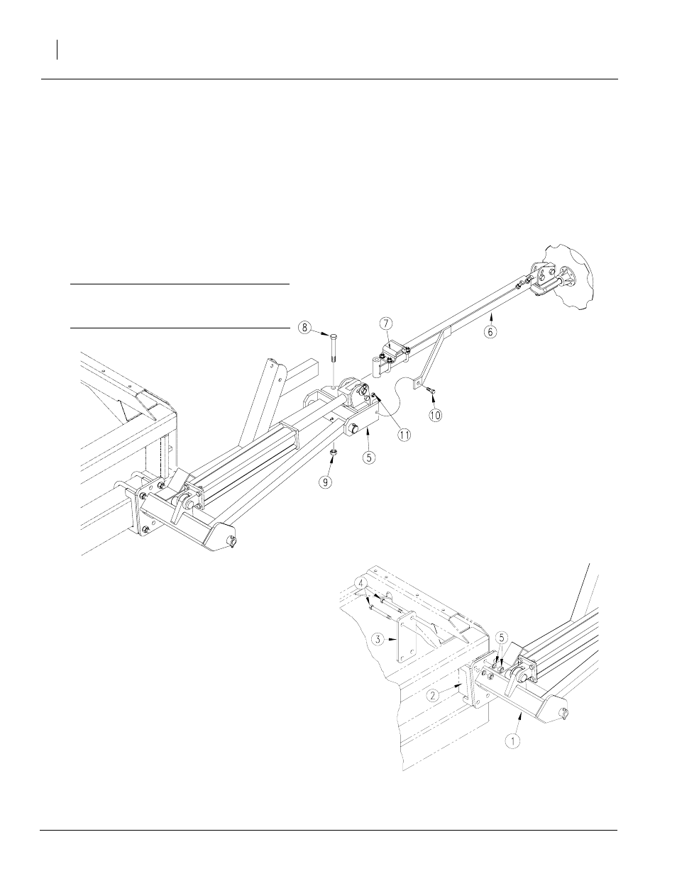
Refer to Figure 2.
Figure 2
Marker Breakaway Assembly
18534
3.
Remove port plugs on cylinder and carefully
unfold first marker section. Rotate hinge sec-
tion (5) into a horizontal position.
4.
Align holes of break-away section (6) with
holes in hinge section. Bolt sections together
with stop block (7) on break-away section fac-
ing up. Use 5/8 inch pivot bolt (8), lock nut (9),
3/8 x 1 3/4 inch, grade 2 shear bolt (10) and
lock nut (11).
IMPORTANT: Be sure shear bolt is a grade 2
bolt. Failure to use a grade 2 bolt can cause
marker damage.
5.
Repeat steps for other marker.
6.
Adjust marker disks so they are square with
ground when markers are lowered in field po-
sition. Refer to Marker Adjustments in opera-
tor’s manual.
Marker Assembly, 1515 Alternate Location
If you will be using the 15-foot bean machine with
a dual-tire tractor, mount markers on the 2 x 5 inch
vertical frame tube to accommodate the gauge
wheels. To mount markers in alternate location,
you will need Great Plains kit 113-686A.
Refer to Figure 3.
1.
Lower bean machine into field position. Allow
9 feet on each end of bean machine for mark-
er assembly.
2.
Mount first marker section (1) on 2 x 5 inch
vertical frame tube (2). Place mounting plate
(3) behind vertical tube. Use 3/4 inch bolts (4)
through marker and mounting plate. Secure
bolts with lock washers and nuts (5).
3.
Complete steps 3 through 6 on page 2 to
complete marker assembly.
Figure 3
1515 Alternate Mounting
17814