Treader gang assembly (optional) – Great Plains 9756PP Predelivery Manual User Manual
Page 16
12
9322-9756PP
Great Plains Manufacturing, Inc.
580-043Q
02/17/2014
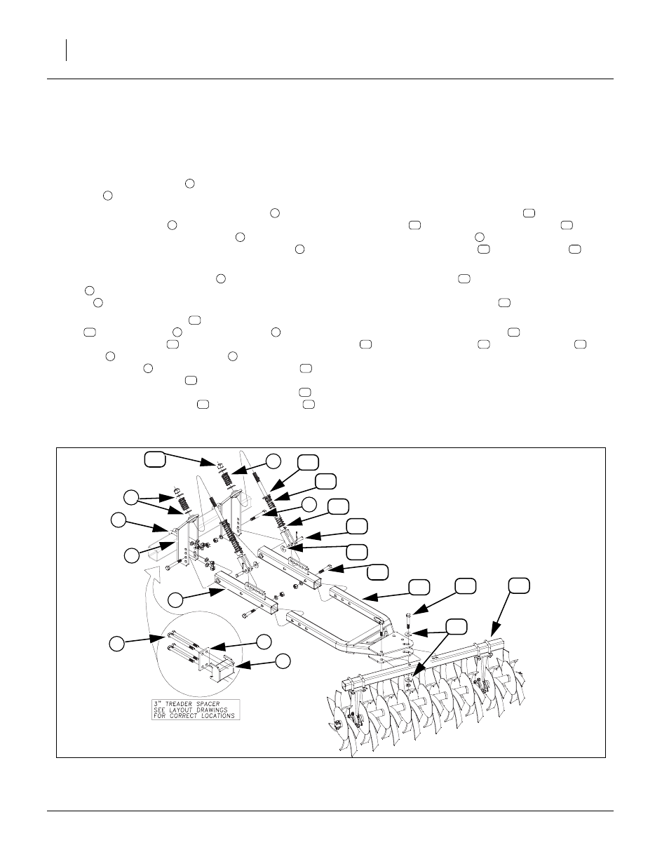
Treader Gang Assembly (optional)
Note: For treader gang placement see “Layout Section”
of this manual. For complete parts breakdown see
“Attachment Section” of Parts Manual.
Refer to Figure 11
40. Install mounting bracket
with 3/4 x 4 1/32 x 5 3/8
u-bolts
, 3/4 lock washers and 5/8 nuts.
41. On models 9744-9756 the treader spacer
and
treader spacer plate
will need installed on center
section between mounting bracket
and rear tube
of center frame. Secure with 3/4 x 10 hex bolts
, 3/
4 lock washers and 3/4 nuts.
42. Attach treader mount brackets
to mounting brack-
ets
, (2nd hole from bottom) with 3/4 x 5 1/2 hex
bolts
, secure with 3/4 lock washers and 3/4 nuts.
43. Remove 1 nylon lock nut
from clevis bolt assem-
bly
, 1 flat washers
and upper spring
. Slide
clevis bolt assembly
through uniball of heavy fold
bracket
, secure 1 flat washers
(one each side
of upper spring
), secure with 1 nylon lock nut
.
Tighten 1 nylon lock nut
down to where there is
about 2 threads showing above nut. Slide collar
up on clevis bolt assembly
until slower spring
is snug against bottom of uniball but do not com-
press spring and tighten set screw in collar to
secure.
44. Remove the 3/4 x 2 1/2 clevis pin
from clevis bolt
assembly
. Attach clevis bolt assembly
to
treader mount brackets
(3rd hole from front) with
the 3/4 x 2 1/2 clevis pin
, 3/4 flat washer
and 1/
8 x 1 cotter pin. Bend cotter pin to secure.
45. Slide treader mount
(with hole position and
angled plate orientation shown in layout drawings),
secure with 3/4 x 4 hex bolts
, secure with 3/4 lock
washers and 3/4 nuts.
46. Attach treader gang assembly
to treader mount
with 3/4 x 4 hex bolts
, 3/4 flat washers
(one
on top and one on bottom of plates, secure with 3/4
lock washers and 3/4 nuts.
47. When all rolling harrow assemblies are bolted up to
drag frame, position as shown in “Layout Section” of
this manual and tighten all bolts to specs, See
“Torque Values Chart” on page 15.
1
2
3
4
1
5
6
1
7
10
11
8
9
11
1
8
9
10
10
18
11
19
12
11
11
6
12
13
14
15
16
14
15
17
Figure 11
Treader Gang
43032
8
6
5
2
9
1
7
4
3
11
15
14
13
12
10
17
16
15
18
19