Depth stop tube assembly, Wheel/tire & frog assembly – Great Plains 9756PP Predelivery Manual User Manual
Page 13
Great Plains Manufacturing, Inc.
Assembly
9
02/17/2014
580-043Q
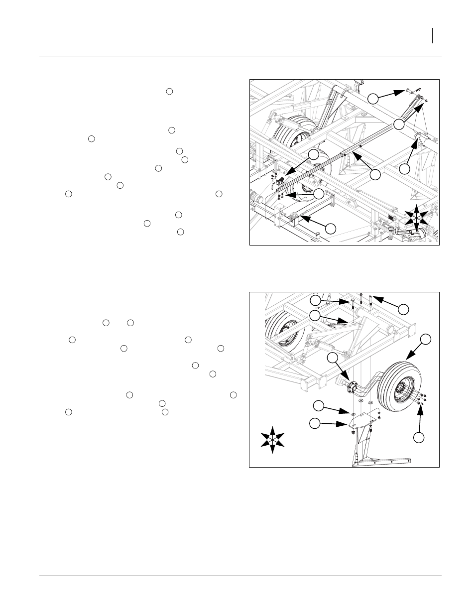
Depth Stop Tube Assembly
Note: The depth stop tube assembly
will be banded to the
rear tube of center frame. Carefully remove banding
from depth stop tube assembly.
Refer to Figure 6
26. Remove the 1/2 x 2 1/2 hex bolts
from the depth stop
assembly
.
27. Slide the depth stop tube assembly
, from rear,
through the square hole of slide tube
in orientation
shown. Remove 1 x 3 3/8 pin
from rear of depth stop
tube assembly
and re-install pin through aligned holes
of torque tube ear
and ear of depth stop tube assem-
bly
. Install the 1.5 x 1.00 x 0.075 flat washer
and 3/
16 x 2 cotter pin. Bend cotter pin over to secure.
28. Re-attach the depth stop assembly
to the front of
depth stop tube assembly
in orientation shown.
Secure with the 1/2 x 2 1/2 hex bolts
, 1/2 lock washers
and 1/2 nuts.
29. Bolt may be tightened to specs, See “Torque Values
Wheel/Tire & Frog Assembly
Refer to Figure 7
Note: Models 9533, 9744 & 9748 the outside wing frogs and
wheel/tire will not be installed.
30. Remove bolts
and
from outside wing frame.Unfold
outside wing and lower machine down to just above the
frog
. Align holes in top plate of frog
and holes in
outside wing frame
. Install the 1 flat washers
between frog plate and bottom of wing frame (all three
holes). Re-install the front 1 x 8 hex bolt
, secure with
the 1 lock nut. Re-install the 3/4 x 6 hex bolts
, secure
with the 3/4 lock washers and 3/4 nuts.
31. Remove the lug nuts
from spindle/hub assembly
.
Install the wheel/tire assembly
to spindle/hub assem-
bly
. Secure with the lug nuts
.
32. Tighten lock nuts snug but do not torque. The rest of
bolts may be tightened to specs, See “Torque Values
Chart” on page 15.
Figure 6
Depth Stop Tube
43021
1
U
D
F
B
L
R
2
6
5
4
3
7
3
1
2
3
4
5
3
6
3
7
2
3
1
Figure 7
Wheel/Tire & Frog
43019
U
D
F
B
L
R
2
8
5
1
6
4
7
3
3
4
1
1
2
5
3
4
8
7
6
7
8