Great Plains PH-20 Operator Manual User Manual
Page 27
25
Section 3 Adjustments
12/29/2011
PH-15, PH-20, PFH-15 and PFH-20 Precision Fertilizer Hitch 148-365M
Great Plains Mfg., Inc.
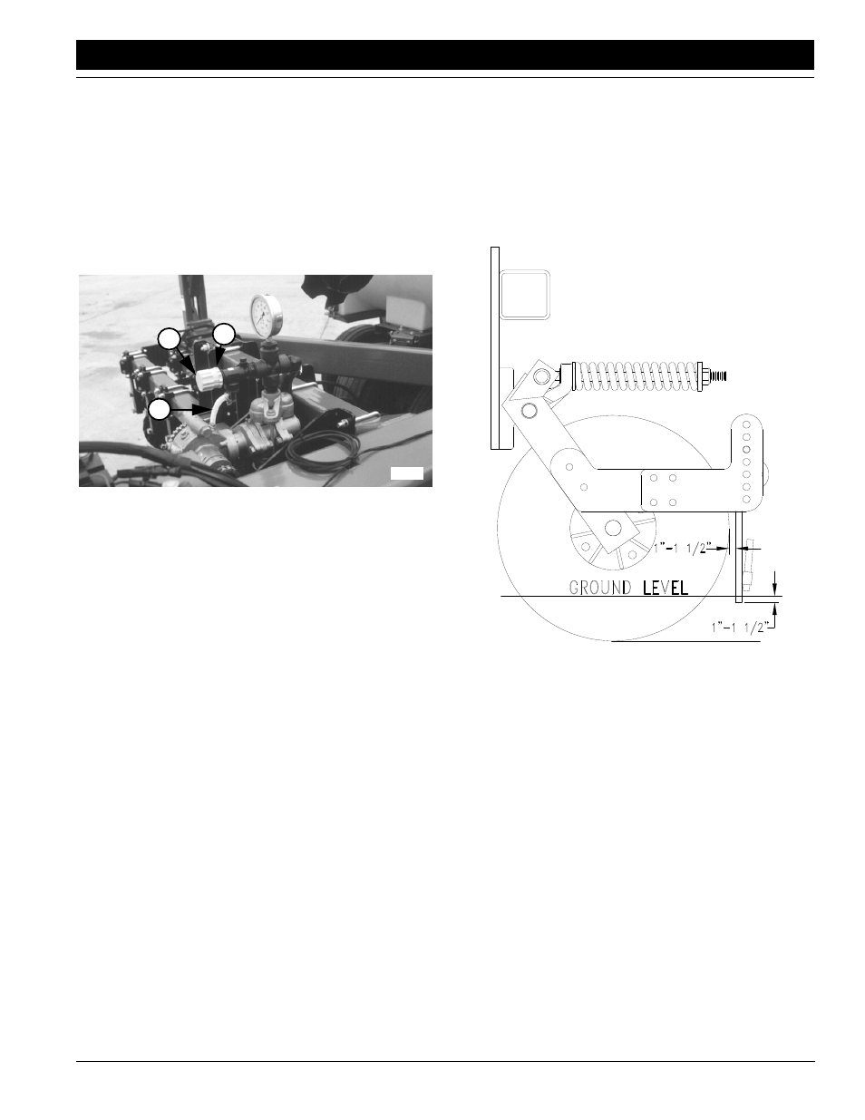
Setting Relief Valve
A relief valve is mounted directly above the pump to pro-
tect the manifold and pump from excessive pressure. Any
product that dumps over the relief valve will discharge
from the dump line (1).
To set relief valve:
1.
Unlock plastic jam nut (2) from relief-valve knob.
2.
Unscrew knob (3) counterclockwise until it loses con-
tact with internal spring.
3.
Screw knob clockwise two turns. Start at this setting.
Figure 3-12
Set Relief Valve
4.
Observe manifold gauge and watch for relief-valve
discharge while operating in the field.
• If valve is dumping product and gauge reads under
85 psi, stop tractor and turn knob clockwise 1/4 turn.
Continue operating at normal field speed. Repeat
this step as needed until no product is discharged
from relief valve.
• If the pressure gauge reads above 85 psi, change to
a larger orifice, following the guidelines in the orifice
selection table. Go to step 2 and repeat steps.
Adjusting Fertilizer Tines
Your main objective when adjusting the fertilizer tine is to
position the nozzle so it sprays into the void created by the
slicing action of the coulter blade. This allows the nozzle to
inject fertilizer to the bottom of the trench.
18050
3
2
1
When positioning tines:
• Set fertilizer tines so bottom of tines are about 1 to 1
1/2 inch below the soil surface. You can set the tines
deeper, but you risk causing excessive wear and
plugging.
• Set tines about 1 to 1 1/2 inch behind the coulter
blade in a vertical or slightly back swept position.
• Set tines in line with the coulter blade.
Figure 3-13
Fertilizer Tine Adjusted Properly
The fertilizer coil tines are adjustable in three ways: side to
side, front to back and up and down. Refer to the following
instructions to adjust the fertilizer coil tines properly.
12411