Great Plains PH-20 Operator Manual User Manual
Page 16
14
Section 2 Operating Instructions
PH-15, PH-20, PFH-15 and PFH-20 Precision Fertilizer Hitch 148-365M
12/29/2011
Great Plains Mfg., Inc.
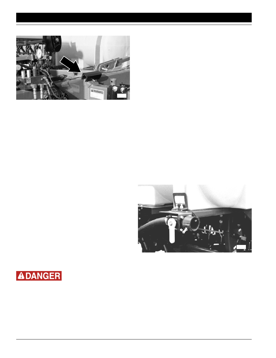
Store channel on support gusset. See Figure 2-3.
Figure 2-3
Cylinder Lock Channel in Storage
4.
Set and calibrate drill seeding rate. Refer to drill oper-
ator’s manual.
5.
Adjust coulters for necessary down pressure and de-
sired depth. Refer to Coulter Depth, “Adjustments,”
page 29, or Coulter Command Adjustments, “Adjust-
ments,” page 29, and Coulter Down Pressure, “Ad-
justments,” page 19, for adjustment instructions.
6.
Adjust drill seeding depth. Refer to drill manual.
7.
Level hitch and drill. Refer to Leveling Adjustment,
“Adjustments,” page 22.
8.
Pull forward, lower coulters and drill, and begin seed-
ing.
9.
After seeding for a short distance, stop with the drill
and hitch in the ground. Inspect the drill for proper op-
eration including the following:
• Confirm that the automatic pivot locks have raised,
so the hitch is free to articulate and track properly on
curves. (See Pivot Locks, page 16, for more infor-
mation.)
• Confirm that seed is being metered.
• Check seed depth.
10. Always lift drill out of ground when turning at row ends
and for other short turns. Seeding and fertilizer appli-
cation will stop automatically as you raise the coulters
and drill for field turns. The hitch’s pivot locks will also
engage while turning.
Fertilizer Application Option
Some chemicals will cause serious burns, lung damage and
death. Avoid contact with skin or eyes. Wear proper protective
equipment as required by chemical manufacturer. Avoid pro-
longed breathing of chemical fumes. Wear respirator as re-
quired by chemical manufacturer. Seek medical assistance
immediately if accident occurs. Know what to do in case of an
accident.
The fertilizer-application system uses a piston pump. The
pump is ground driven. The pump moves fertilizer into a
18150
plumbing manifold mounted along the coulter toolbar.
An orifice is installed under the quick cap on each manifold
outlet. The orifice creates a small amount of back pressure
in the manifold and prevents the outlets nearest the pump
from getting too much of the total flow.
Since the pump is a positive displacement pump, the over-
all application rate is determined by the pump setting
(stroke) and the size of the pump driver sprocket. The size
of the orifice does not affect the application rate.
To operate the liquid-fertilizer system, follow these steps:
1.
Choose a sprocket range and pump setting for your
desired application rate. Refer to Fertilizer Application
Rates, “Adjustments,” page 23.
2.
Adjust driver sprocket and pump setting as necessary.
Refer to Adjusting Fertilizer Rates, “Adjustments,”
page 23.
3.
Choose proper orifice to match your application rate.
Install proper orifice plates. Refer to Orifice Plates,
“Adjustments,” page 24.
4.
Adjust fertilizer tines to correct position. Refer to Ad-
justing Fertilizer Tines, “Adjustments,” page 25.
5.
Set manifold relief valve. Refer to Setting Relief Valve,
“Adjustments,” page 25.
6.
Fill fertilizer tanks.
a.
Connect nurse-tank hose to quick-fill coupler
shown in Figure 2-4. Lock hose in place with cam-
lock levers.
Figure 2-4
Quick-Fill Coupler
18131